IoT Nixie Tubes
Every day I make a cup of coffee, organize a list of the things I want to do that day, and try to work through it. Every time I finish one of the tasks, I mark it as complete. By the end of the day, ideally there are no things left on the list, but if there are, I’ll move them into a backlog and start fresh the next day.

There isn’t a clever name for this system like “Getting Things Done”, I believe this is just called “Being a Human Being That Does Their Job”, but I’ve always wondered if there was a way to make completing tasks more exciting. Yes, there should be an innate satisfaction in just checking off tasks that you do, but what if there was something more tangible?
When I was growing up, my dad had a digital clock that he displayed next to his record player that looked like this:
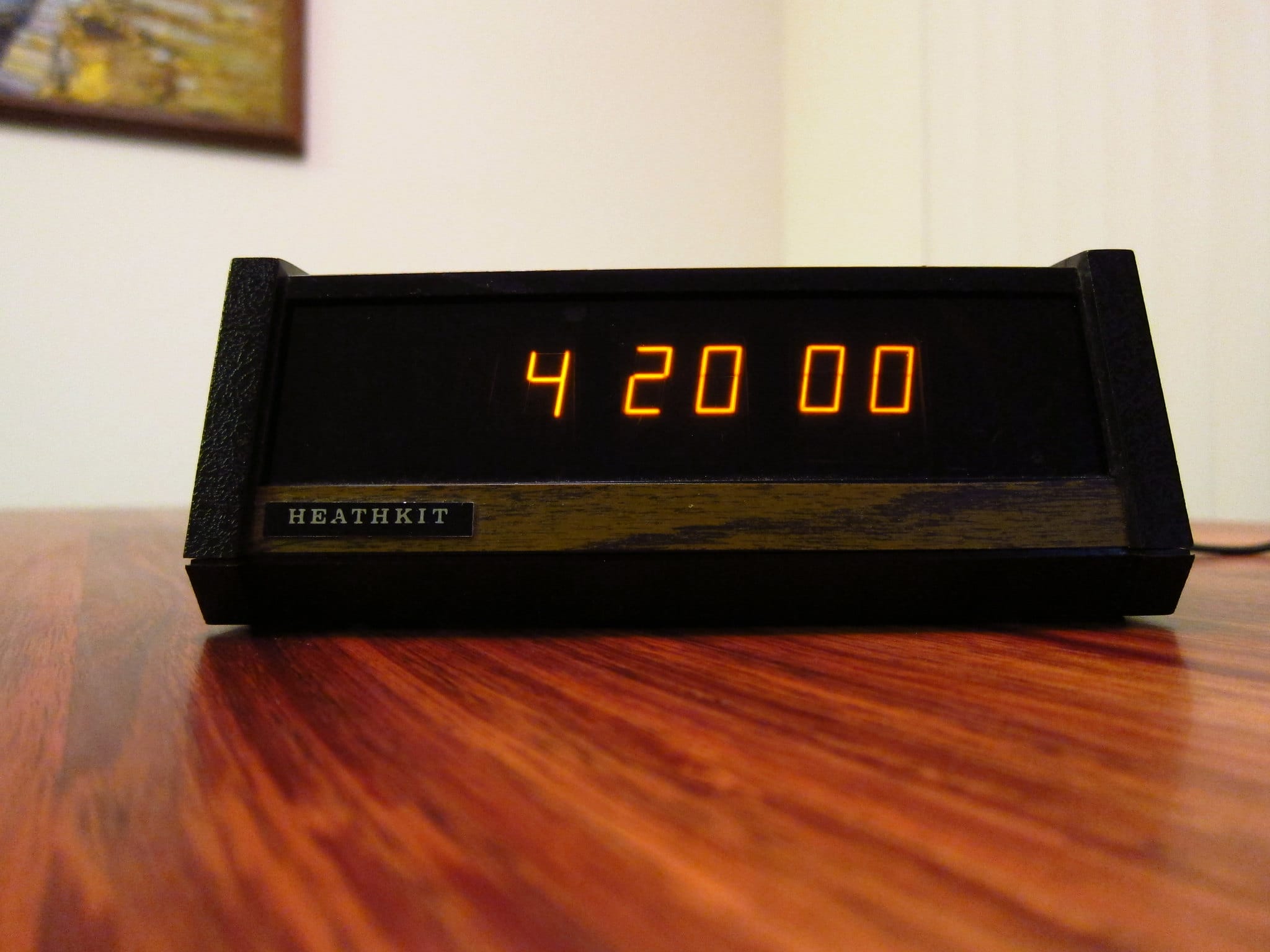
One day I asked him, what’s the deal with the crappy LED clock in the living room and he proudly told me that he had built it himself, from a kit. What he didn’t tell me is that around the same time, probably in the 70s, LEDs had started to completely replace nixie tubes. And while LEDs are smaller, safer, and more reliable than nixie tubes, nixie tubes have the advantage of looking awesome.
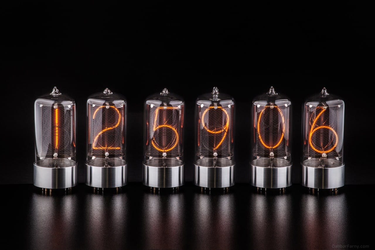
There’s a growing community of nixie tube enthusiasts and they seem really intent on building clocks.


They buy a bunch of these tubes, figure out how to wire them up, build interesting bases for them to sit on, program a way for them to keep time, and sell them on Etsy to other nixie tube enthusiasts. Or at least, they try to sell them. If you want a clock with hours, minutes, and seconds, that’s 6 tubes to acquire, and large nixie tubes are kinda expensive. Clocks like these will cost you well over $1000.
Let’s say there’s a handful of people that can actually afford these things. Presumably once these clock builders have saturated that market, they’ll want to cater to regular people. Regular people can’t afford 6 large nixie tubes, but they might be able to afford one. But what can you do with one nixie tube? Well, I guess you can make a single digit clock:

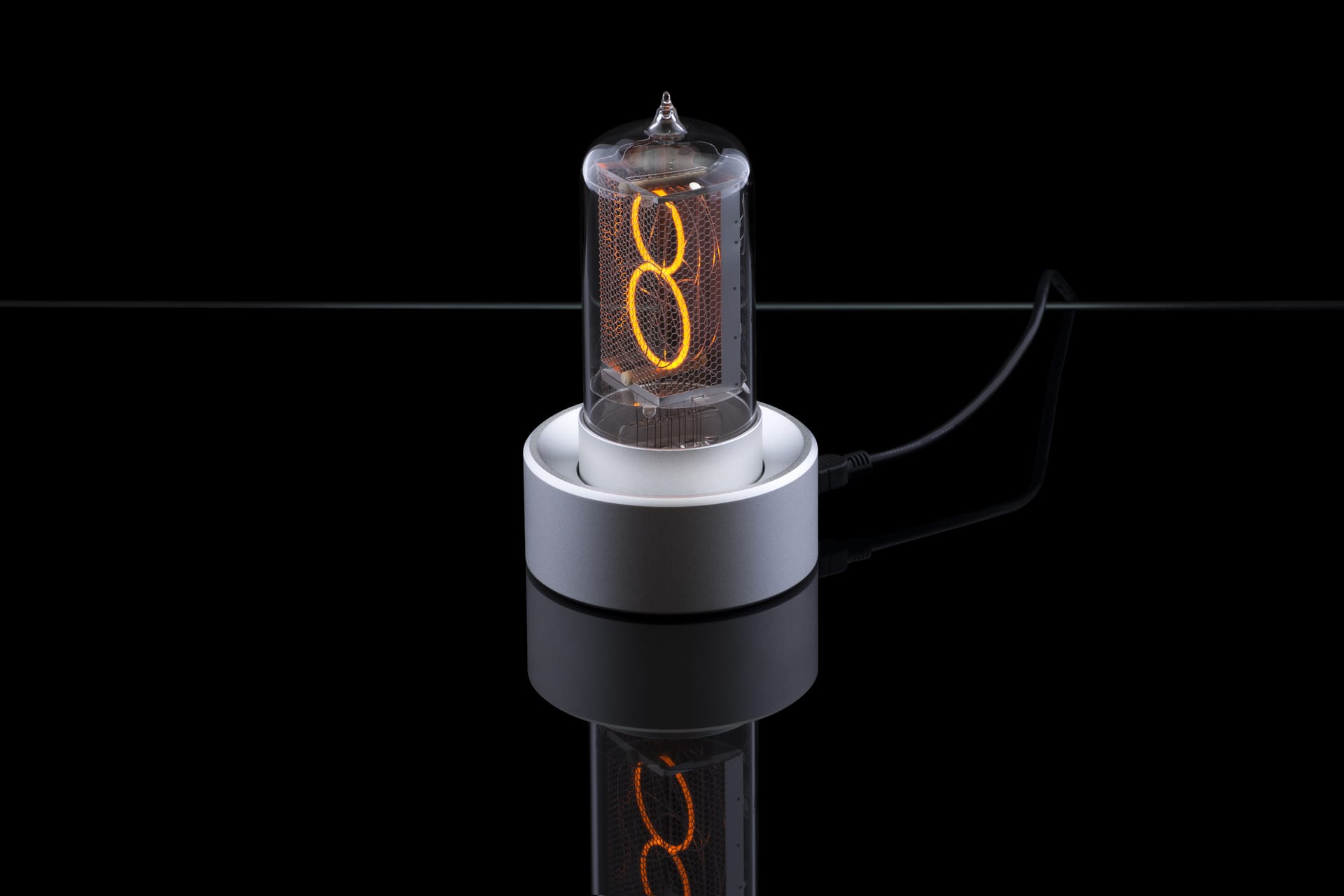
How does a single digit clock work? It flashes the time, one digit at a time.
This seems like a bad idea. No one wants to tell time this way. It does look pretty cool, though.
It seems that you could take a single digit nixie clock and have it display the number of tasks that you had left for the day. Every time you completed a task, the number would go down. Watching that number go down seems like it would be pretty satisfying. And at the end of the day, hopefully it would display 0, but if not you could just move the remaining tasks to your backlog and have it display 0 because the point here is not to do all the tasks but to feel like you’ve accomplished something.
Unfortunately, all of the prebuilt single digit nixie tube clocks that I could find are self-contained units - they don’t connect to the Internet and if they do, it’s only to synchronize the correct time to them.
So let’s accomplish something. Let’s build one ourselves.
Selecting a tube
Nixie tubes come in a lot of different sizes but I wanted one with a giant digit. If you sort this list by symbol height (not an exhaustive list, but the person running the site seems to have a lot of tubes!), two of the largest ones are the Z568M and the IN-18, both with 50mm digits.
The Z568M is the largest European nixie tube. It has a red coating around it to filter out the blue glow, but they also produced the Z5680M which was the same tube but clear.
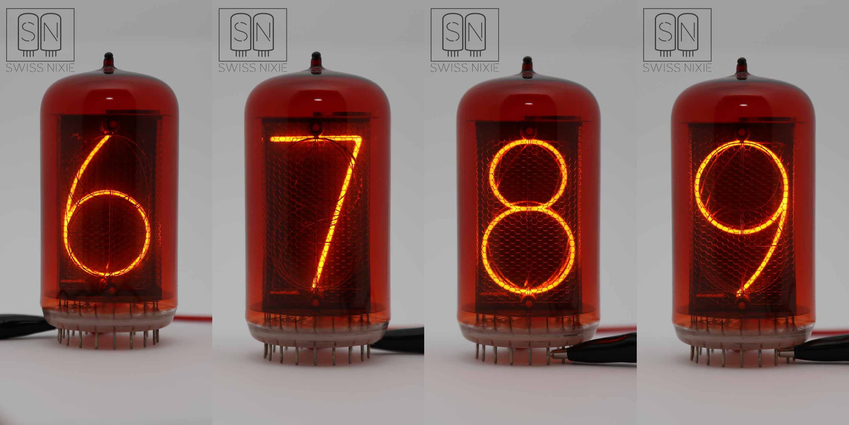
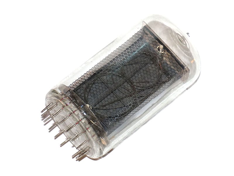
IN-18 is the largest Russian nixie tube, it’s a little skinnier and has elongated digits.

I’ve found that the Z568M sells for around $300-500 while the IN-18 runs around $70-100. These are usually new old stock and as far as I can tell there are just boxes and boxes of IN-18s sitting around in the Ukraine.
Alternatively, two companies seem to produce new versions of these tubes.
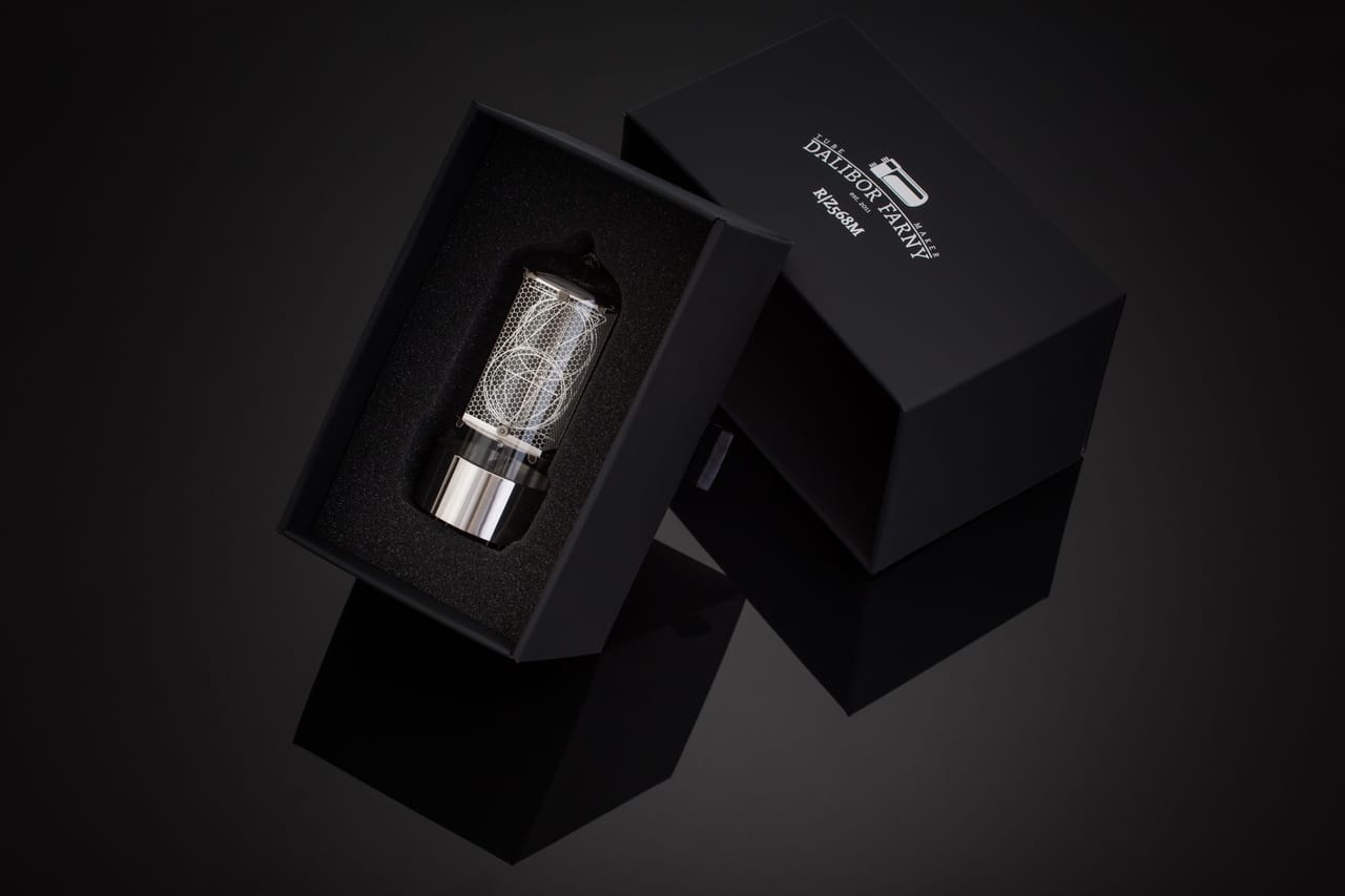
Dalibor Farny sells the R|Z568M, which is a beautiful “resurrection” of the Z568M, although it’s clear like the Z5680M. It costs $155 and comes with a black or stainless steel base.
Millclock makes a similar tube called the ZIN-70 ($129) and a “reborn” version of the IN-18 called the ZIN-18 ($99).
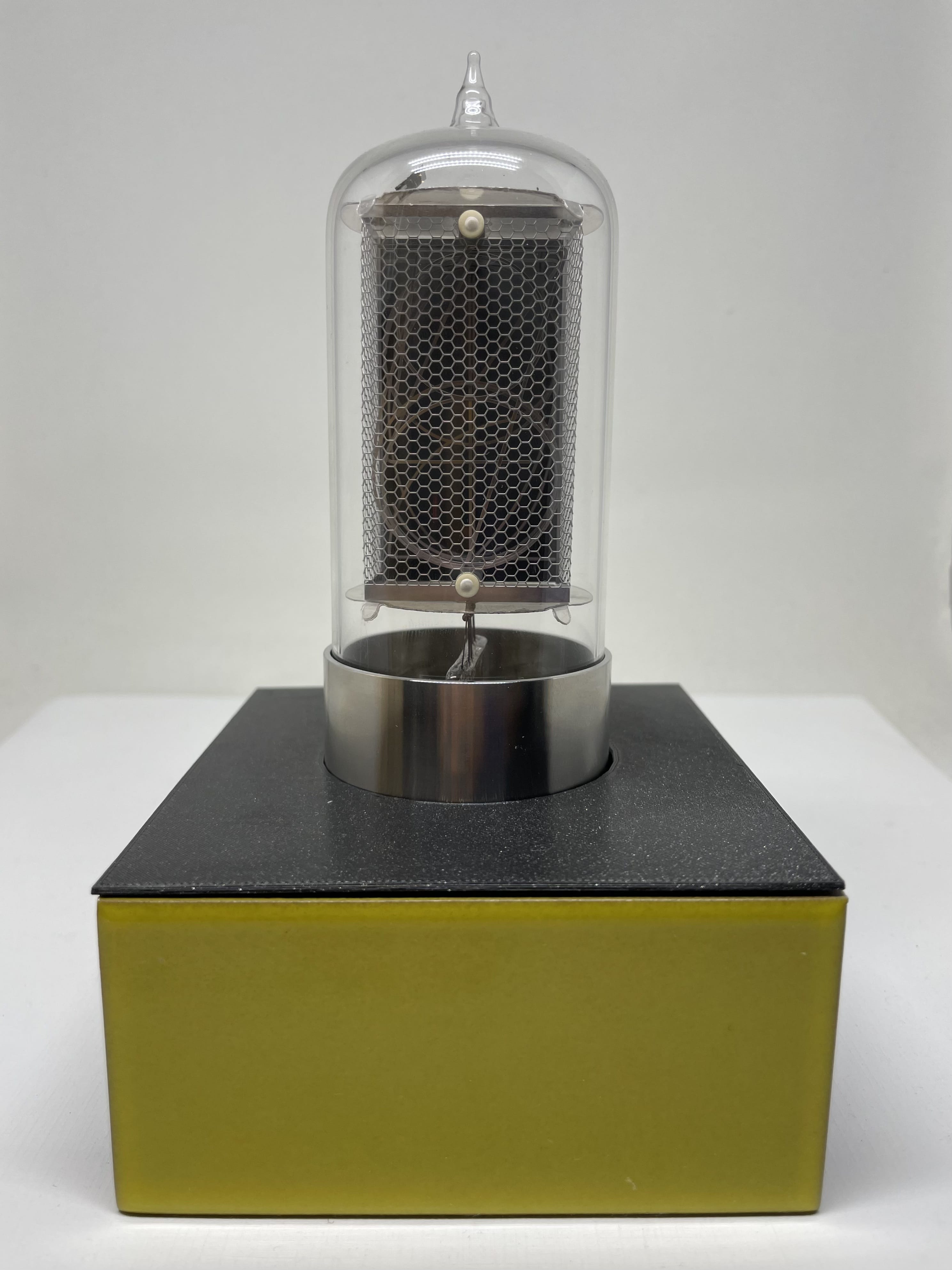
I ended up buying Dalibor Farny’s R|Z568M tube.
Once I had the tube, I needed a way to power it and also a way to set the digits on it.
Powering the tube
Nixie tubes require high voltages to illuminate. The tube that I purchased needs 170 V to ignite. After doing some research, I discovered that what I needed was a step-up converter that takes a low voltage and boosts it to the higher voltage.
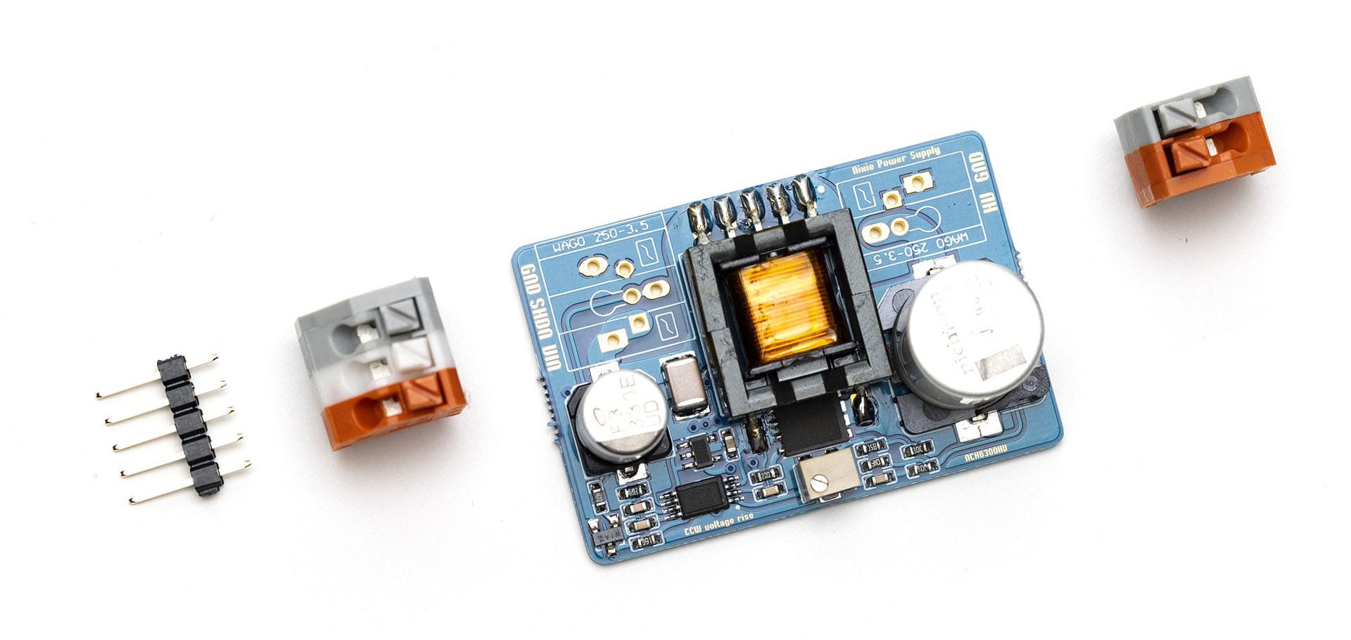
One of the downsides of working with voltages like these is the fact that they can kill you. Almost every component I purchased having to do with Nixie tubes would remind me of this fact. Like many things, after someone designs and produces a module like this, it is immediately replicated and counterfeited, often with lower quality components. This is why when I decided on the NCH6300HV DC-DC booster, I bought it directly from the manufacturer.
This is what it looks like:
It took me a little while to figure out what I was supposed to do with it.
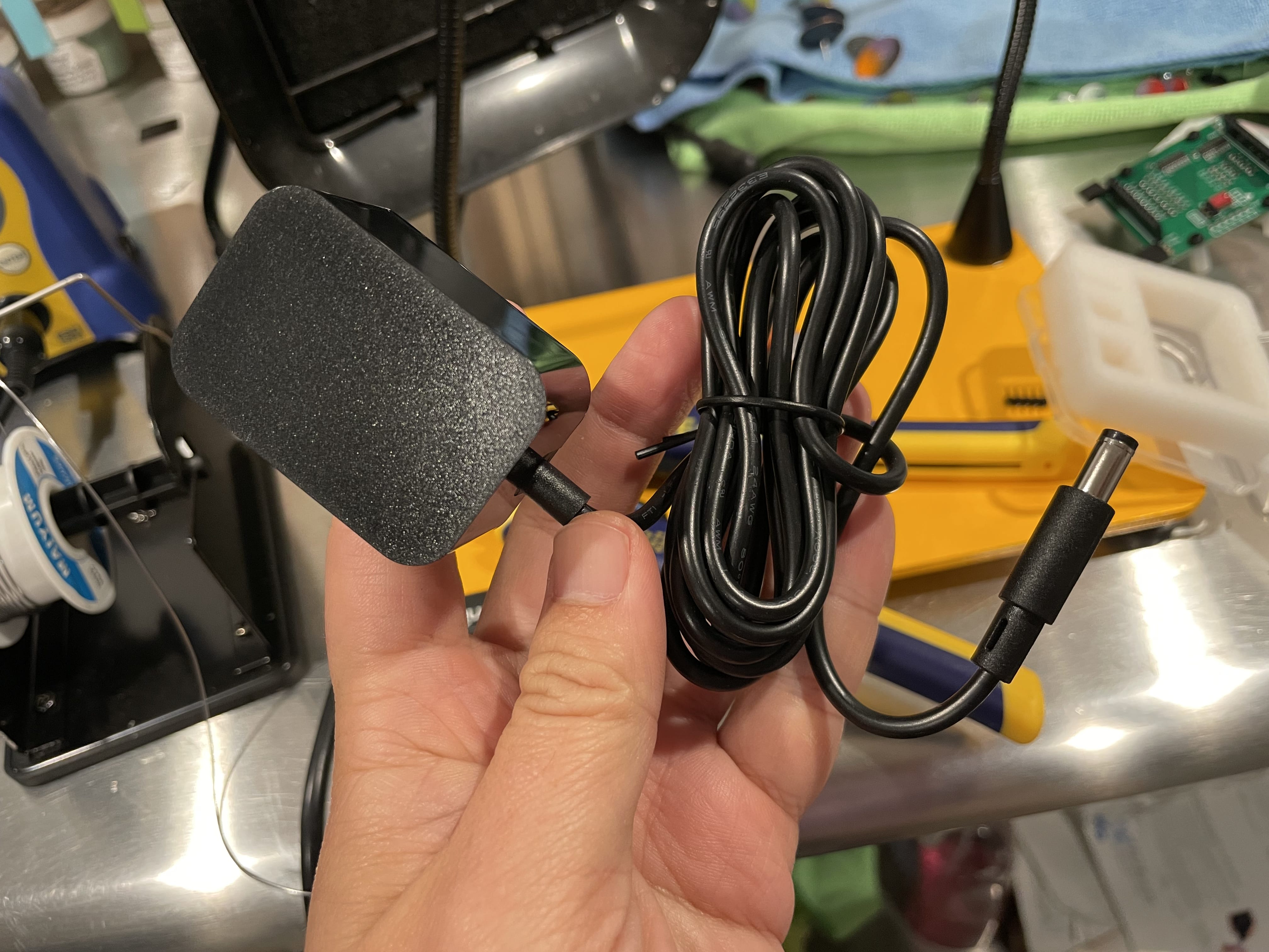
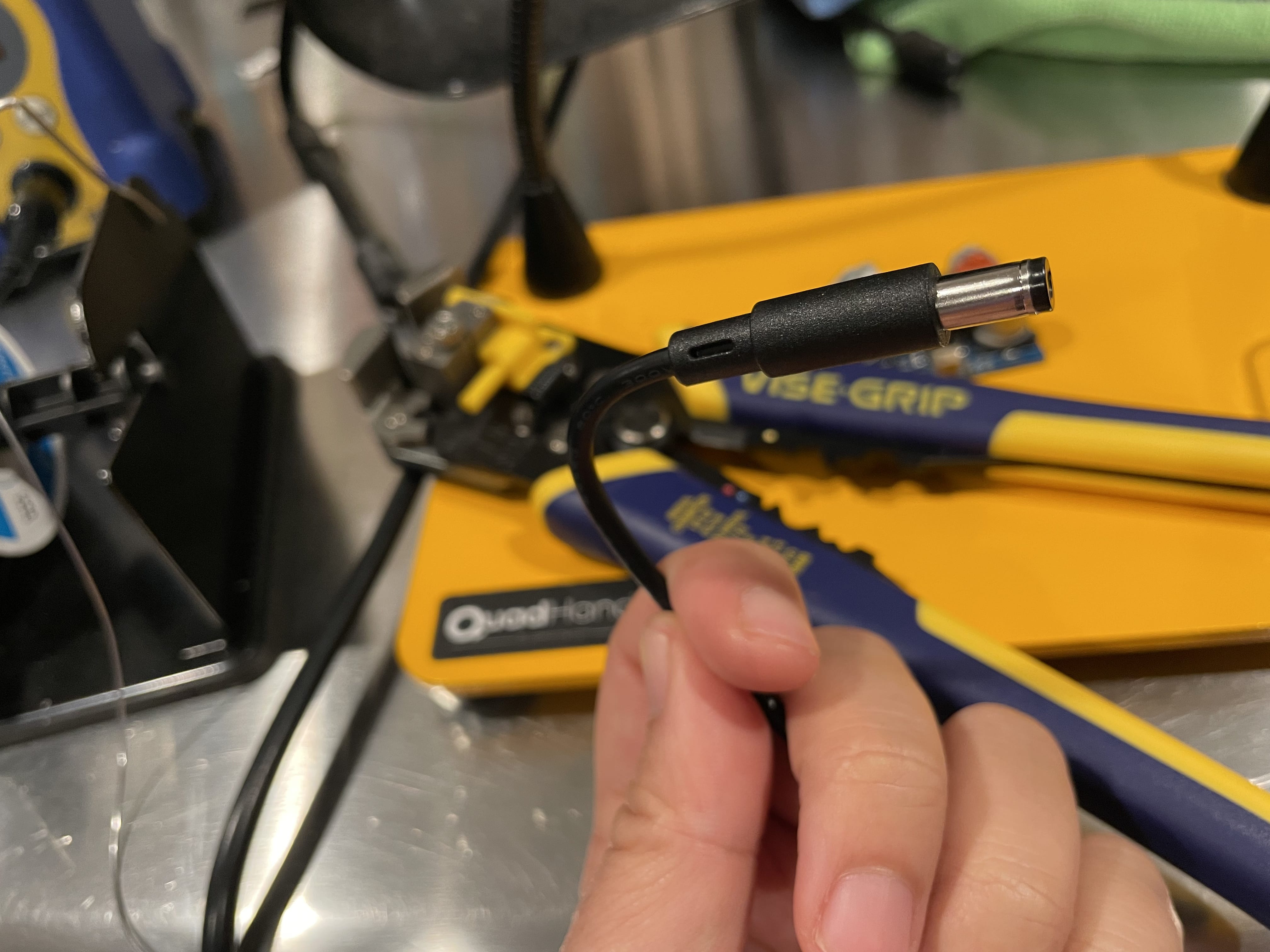
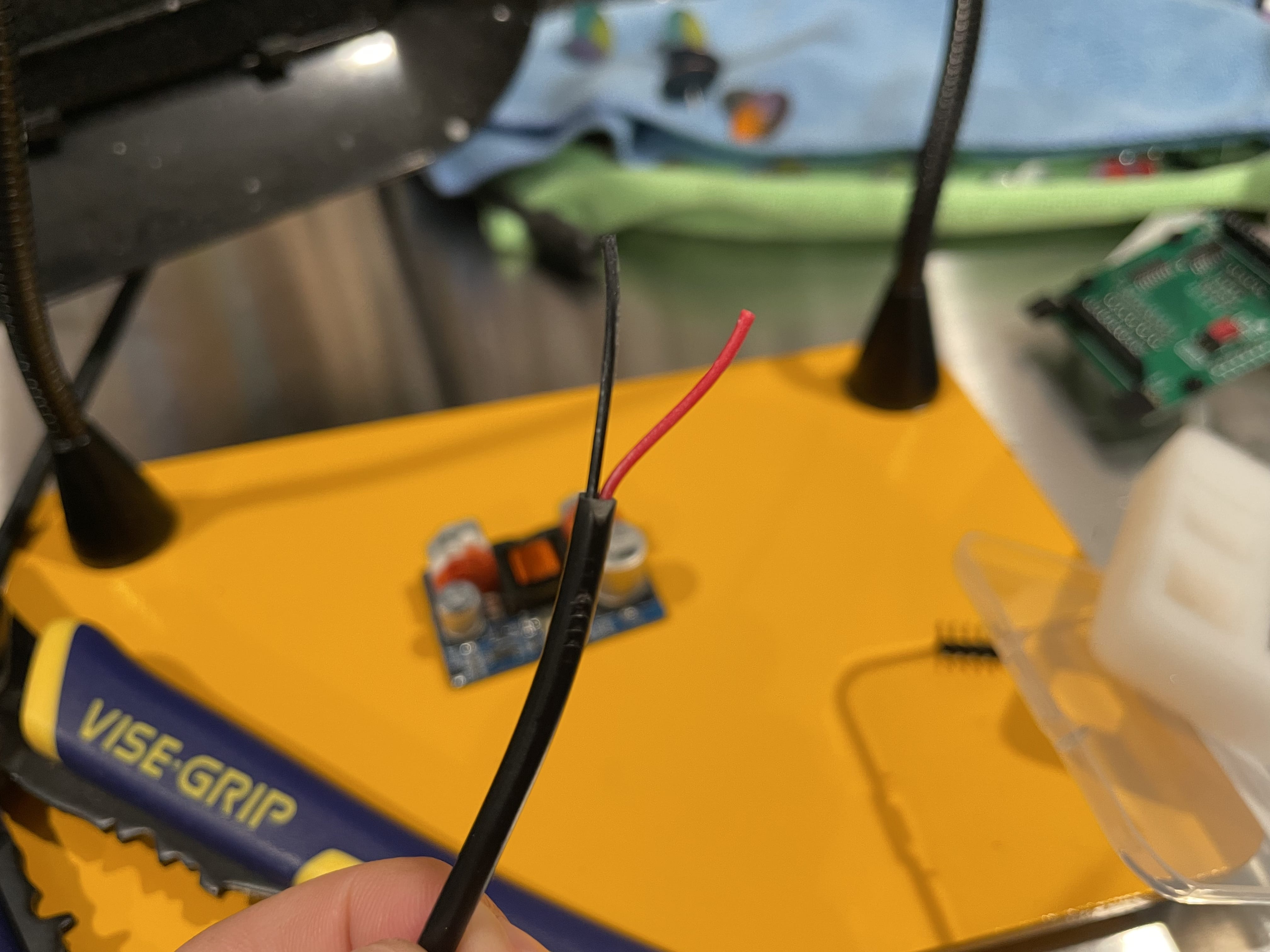
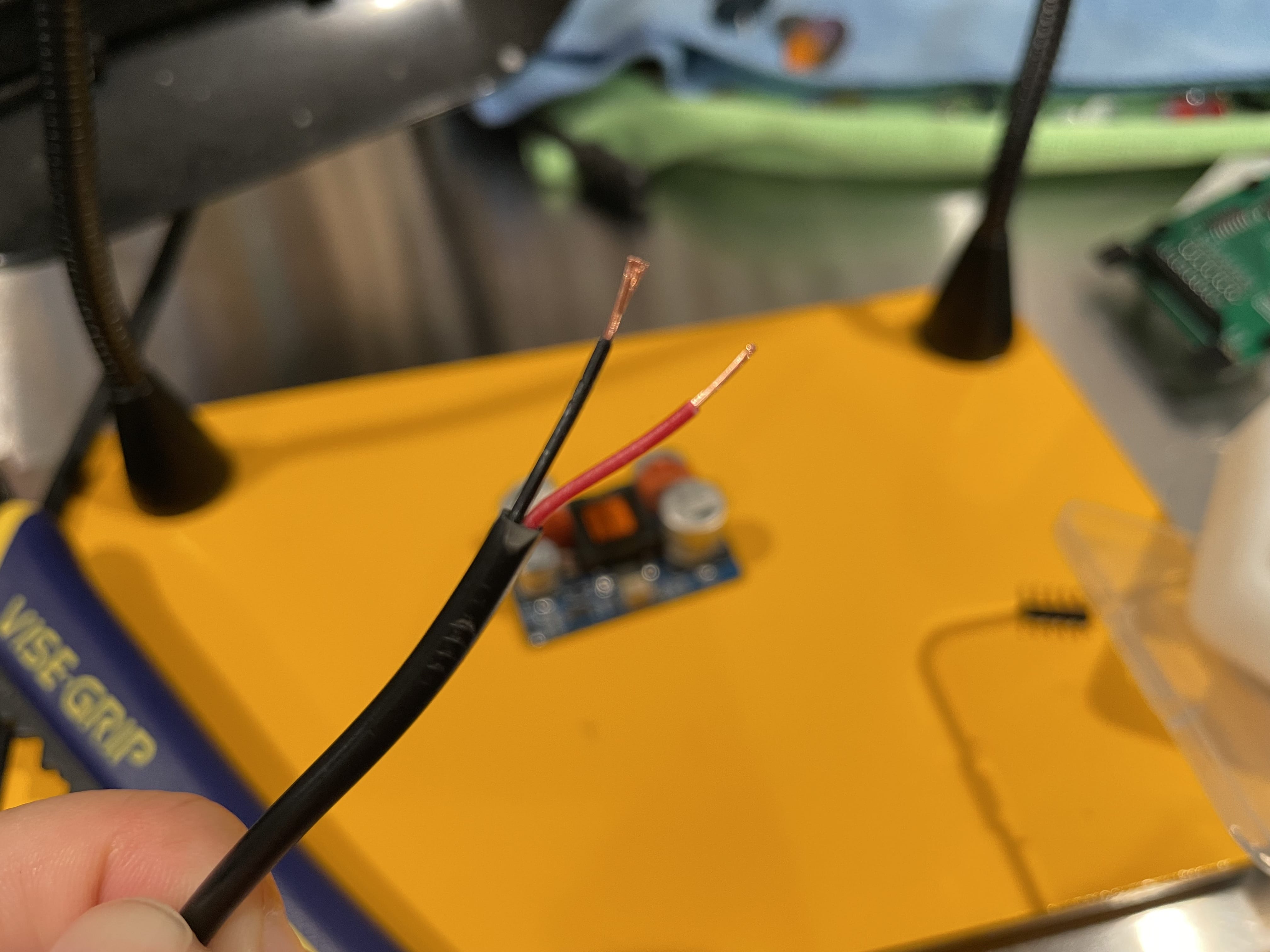
I took a 5V power supply and cut off the end of it, which revealed two cables, power and ground.
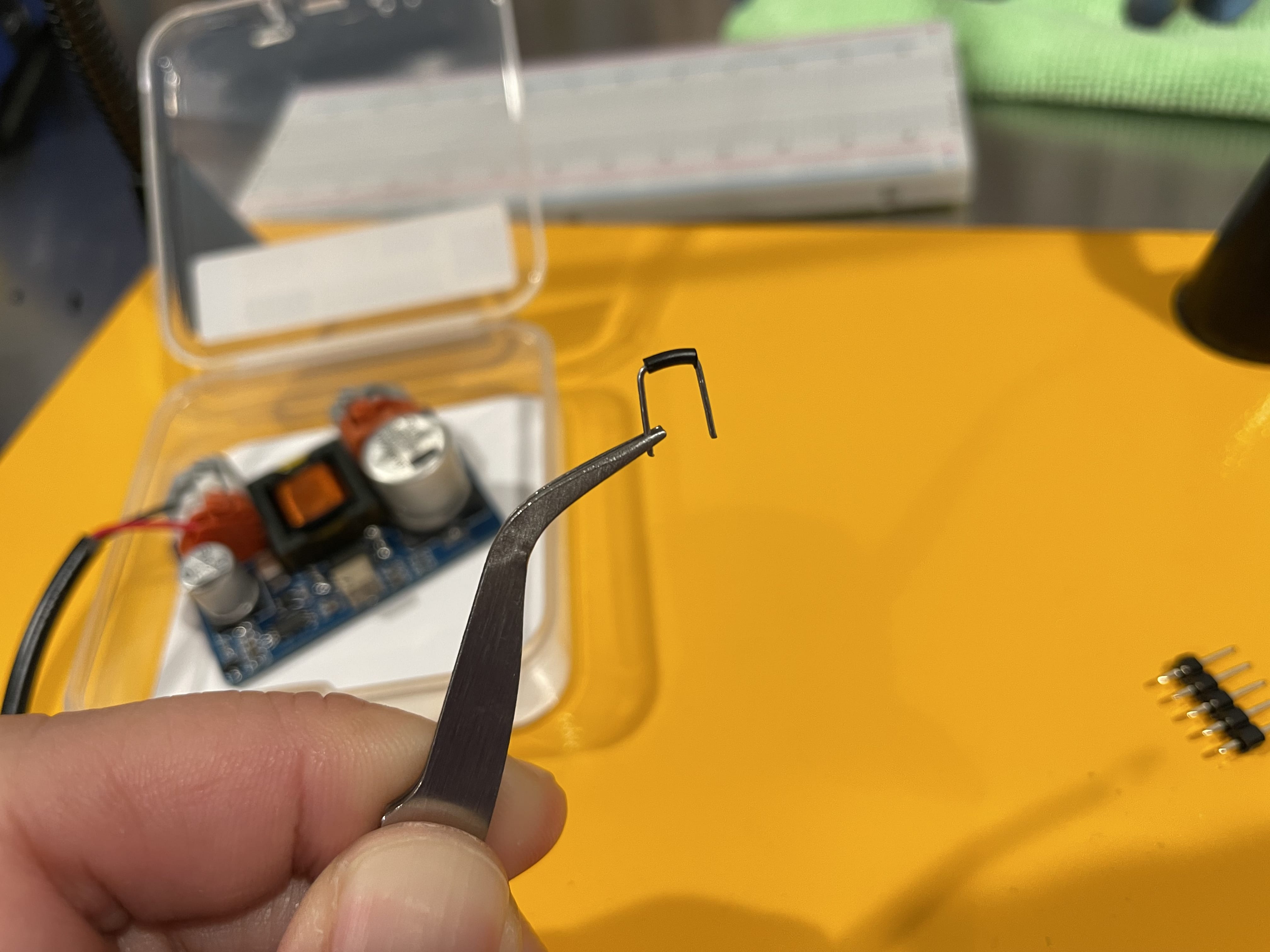
Then I stripped those cables, soldered the wire terminals onto the module, and stuck them into the input wire terminal.
Next I took some 20 AWG wire and stuck it in the output wire terminal, ran those wires to my multimeter, plugged in the power supply and… the multimeter reported some really low voltage.
I re-read the product page for the module and discovered that on the input wire terminal, the white connector needs to be connected to power to actually enable high voltage. So I took a breadboard jumper wire and jammed it between the white connector and the power connector.
This time the multimeter read 126 V. Not quite?
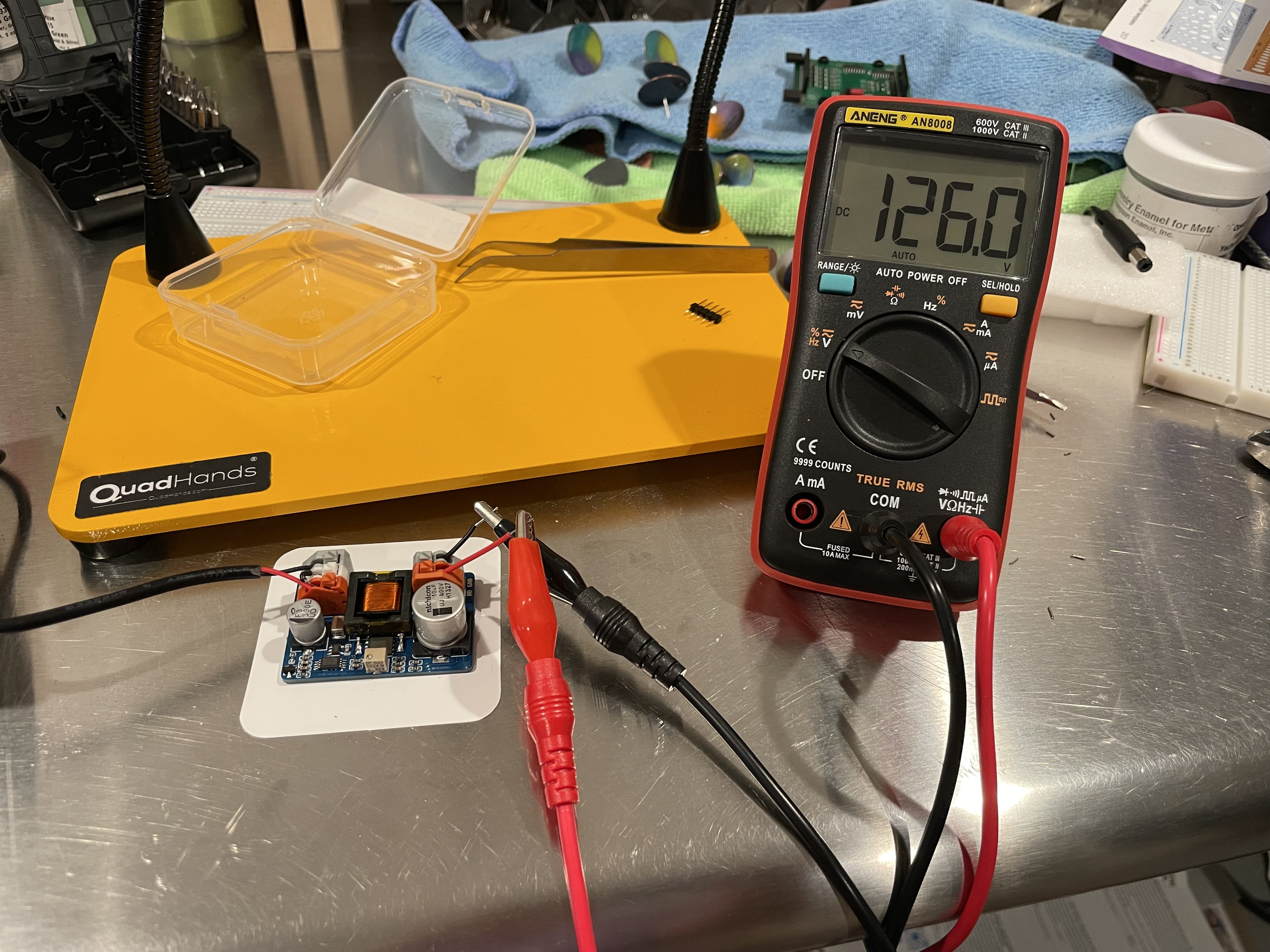
Re-reading the product page a second time, I noticed that one of the reviews mentioned a “multi-turn pot”, which I determined to be the potentiometer in the bottom of the module. Sure enough, taking a jeweler’s screwdriver and slowly turning it to the left increased the voltage until it reached 170 V on the multimeter, at which point I stopped turning it and celebrated brute forcing my way into high voltage.
One thing I noticed is that immediately after disconnecting the power supply, the multimeter still registered a significant amount of voltage and took about a minute to fully drop to 0. I’d been very careful not to touch the output wires or module itself while the power was on, but from that point forward, whenever I turned off the power supply, I would set a timer on my phone for 60 seconds and continue to treat the module as “live” until the timer went off.
Setting the digits
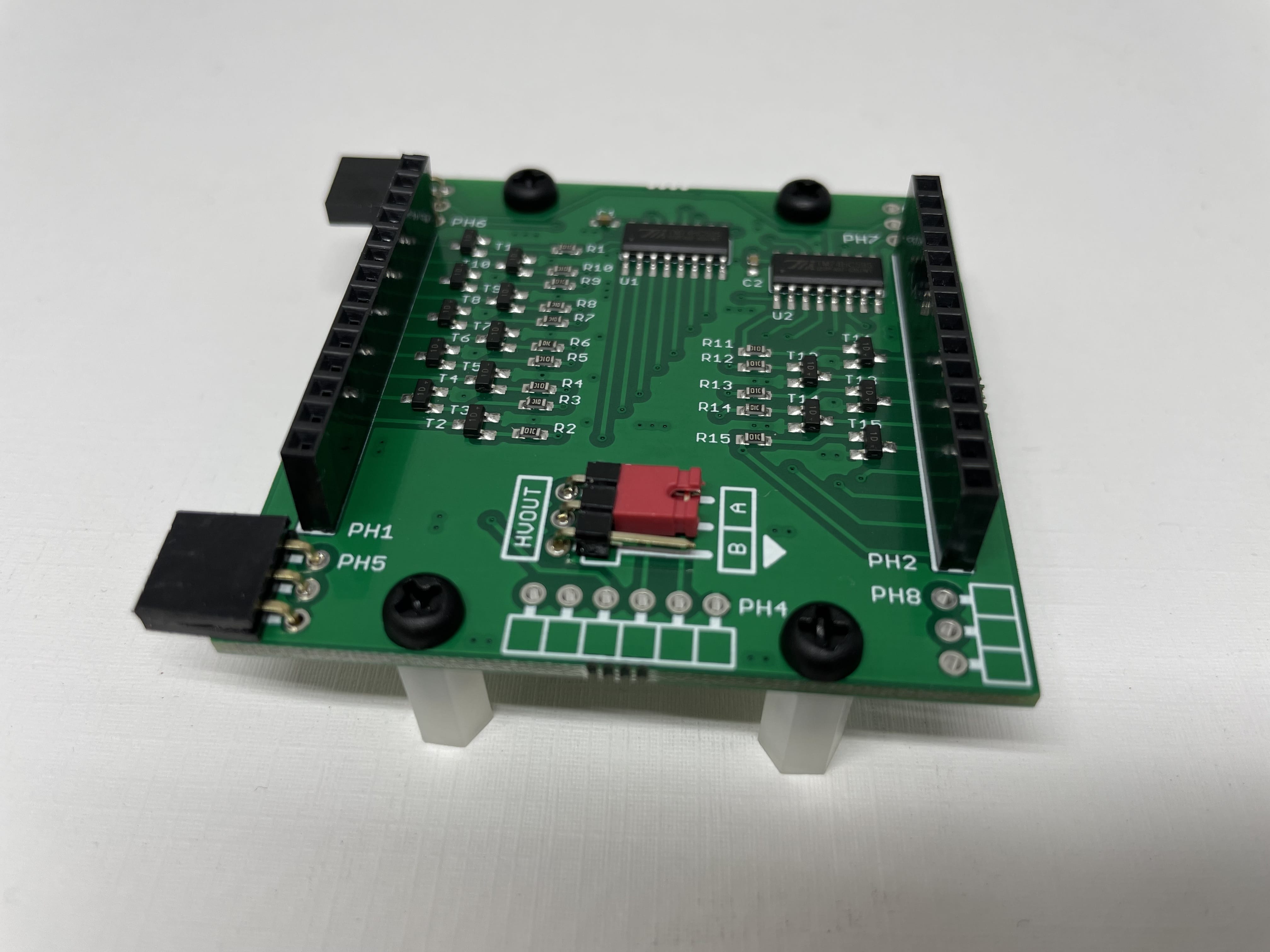
Now that I could power the tube, I needed a way to set the digits. I found a project called the Nixie Socket Driver. It consists of two parts, the socket driver and the socket itself.
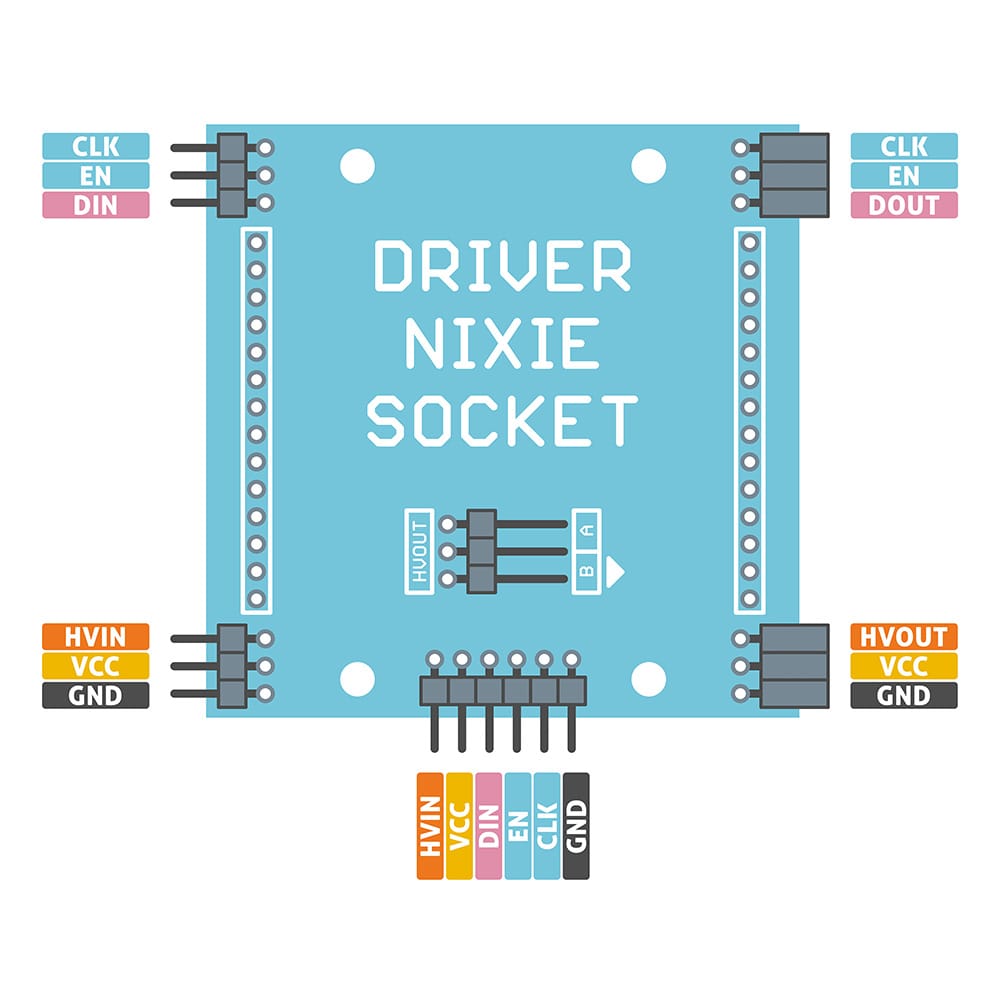
The socket driver has three control inputs (CLK, EN, DIN) which you use to specify which digit to display. You can wire up a device like a ESP8266 or ESP32 to the control inputs and power the driver board, while also supplying the high voltage which it delivers to the tube.
The socket has pin sockets for the nixie tube to go into, a resistor for limiting the high voltage, and pins to connect to the socket driver.
The two part system means that you can buy different sockets for different nixie tubes and change them out. And the socket drivers can be run in series, so if you wanted to run more than one nixie tube, you can leverage the same high voltage for all of them and drive them all from the same device.
I ordered a socket for my tube and a socket driver. I’m not sure exactly what I was expecting, but perhaps I should have paid more attention to the “self-assembly kit” or “pin headers require soldering” parts of the description.
Here’s what was in the socket box:
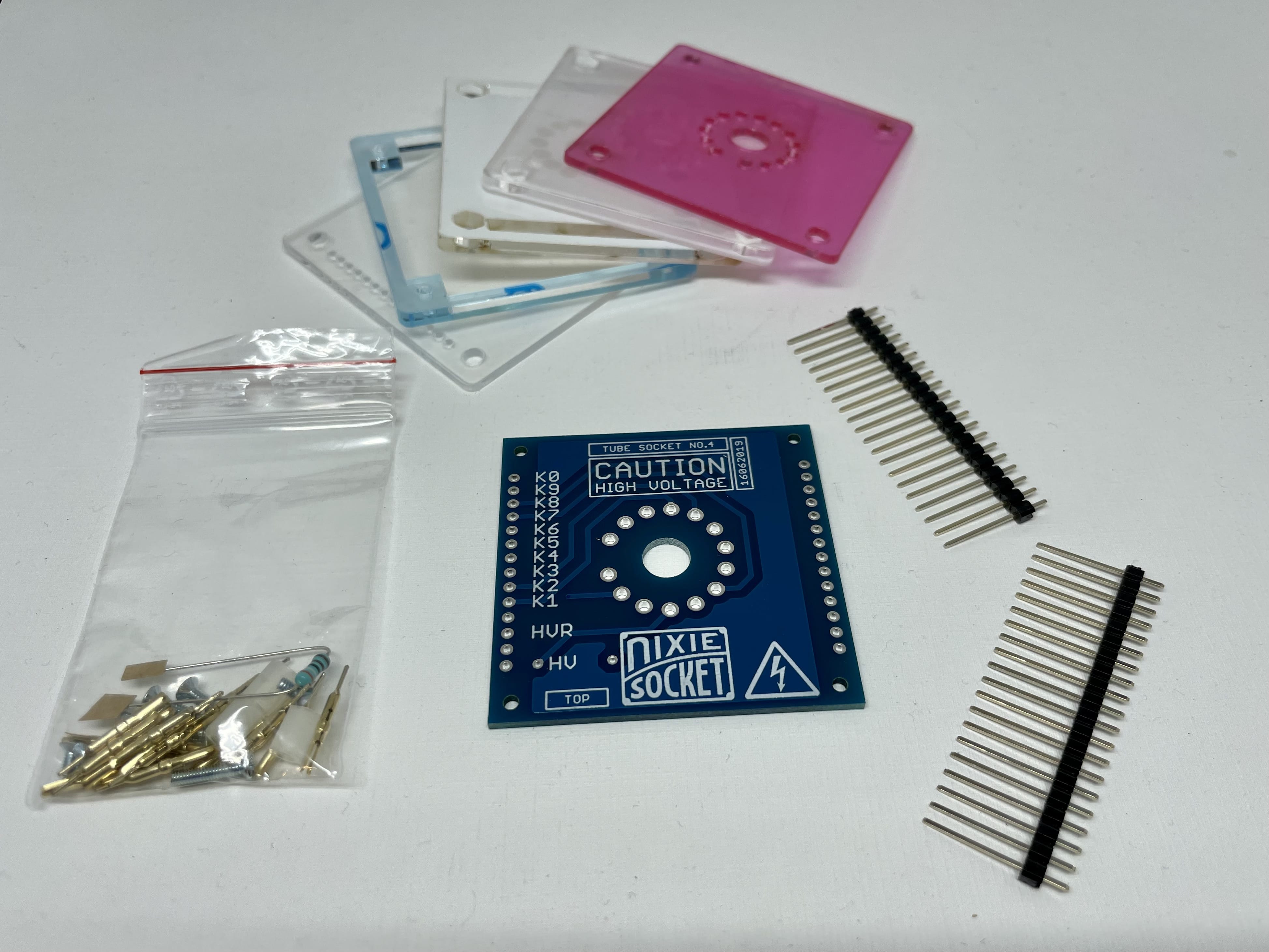
The assembly instructions are pretty clear. First you stick the pin sockets in, solder them, and cut the excess pins off the bottom with some wire cutters.
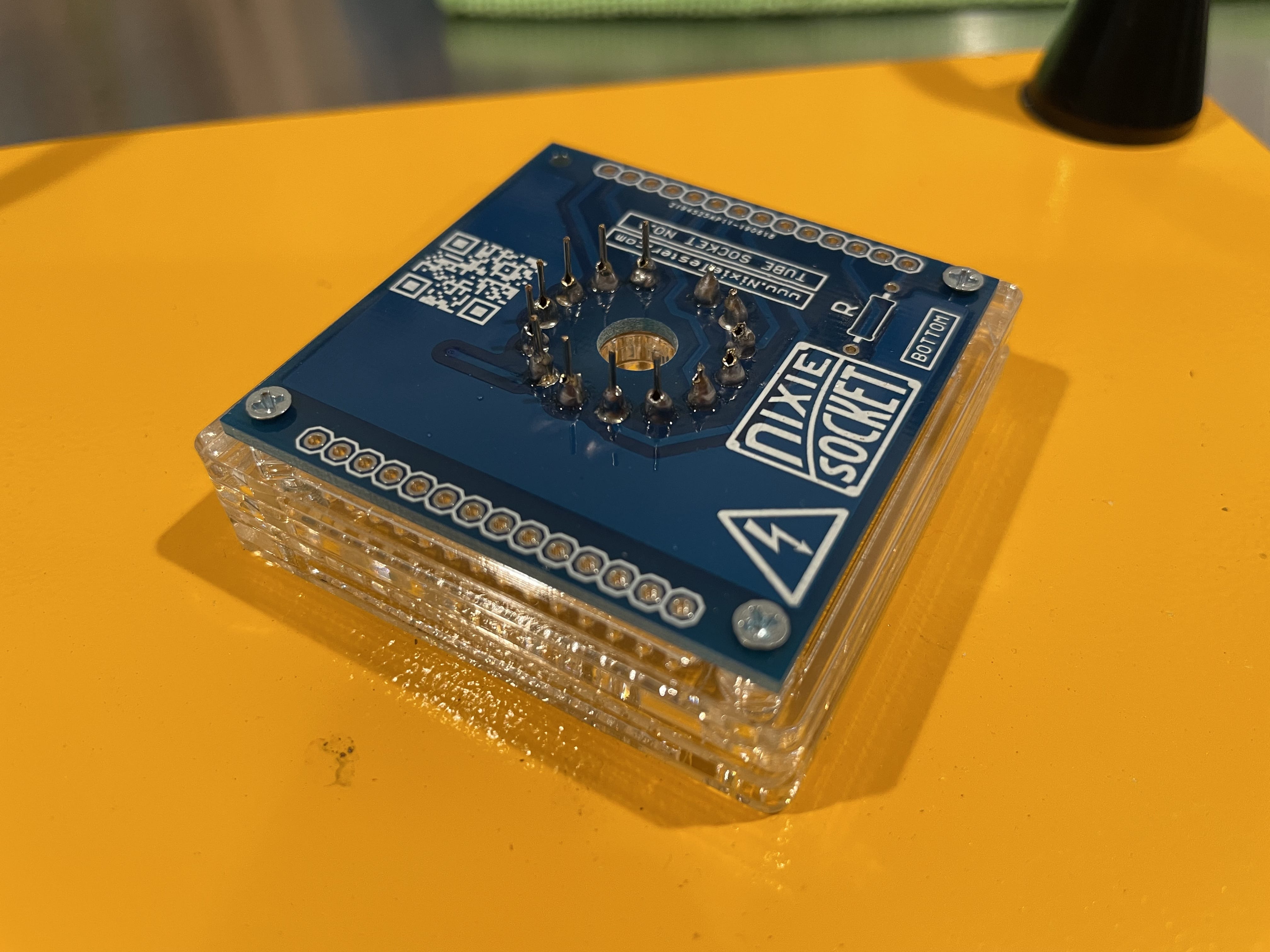
Then you solder the pin headers on, this is the part that will stick into the socket driver board.
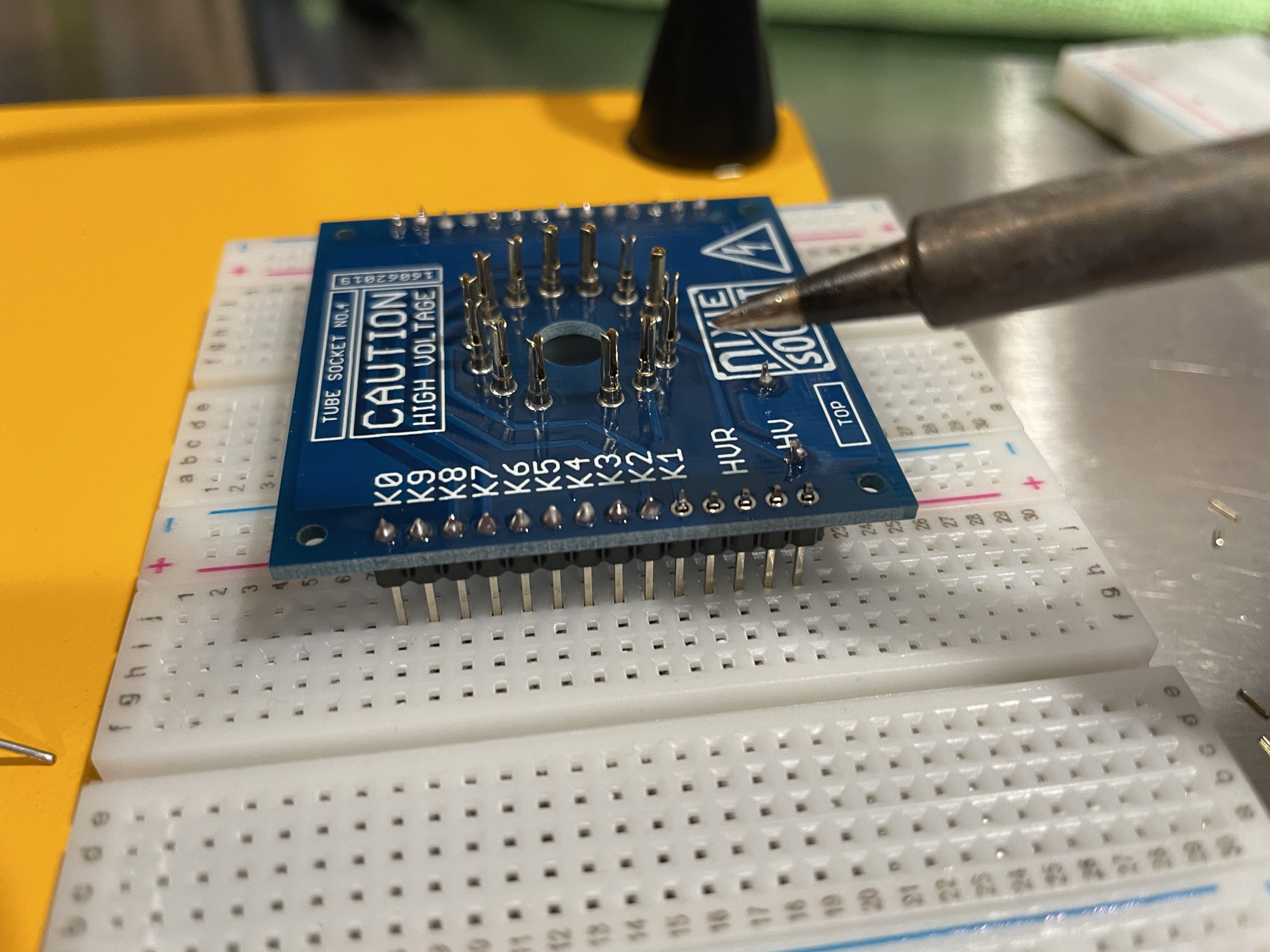
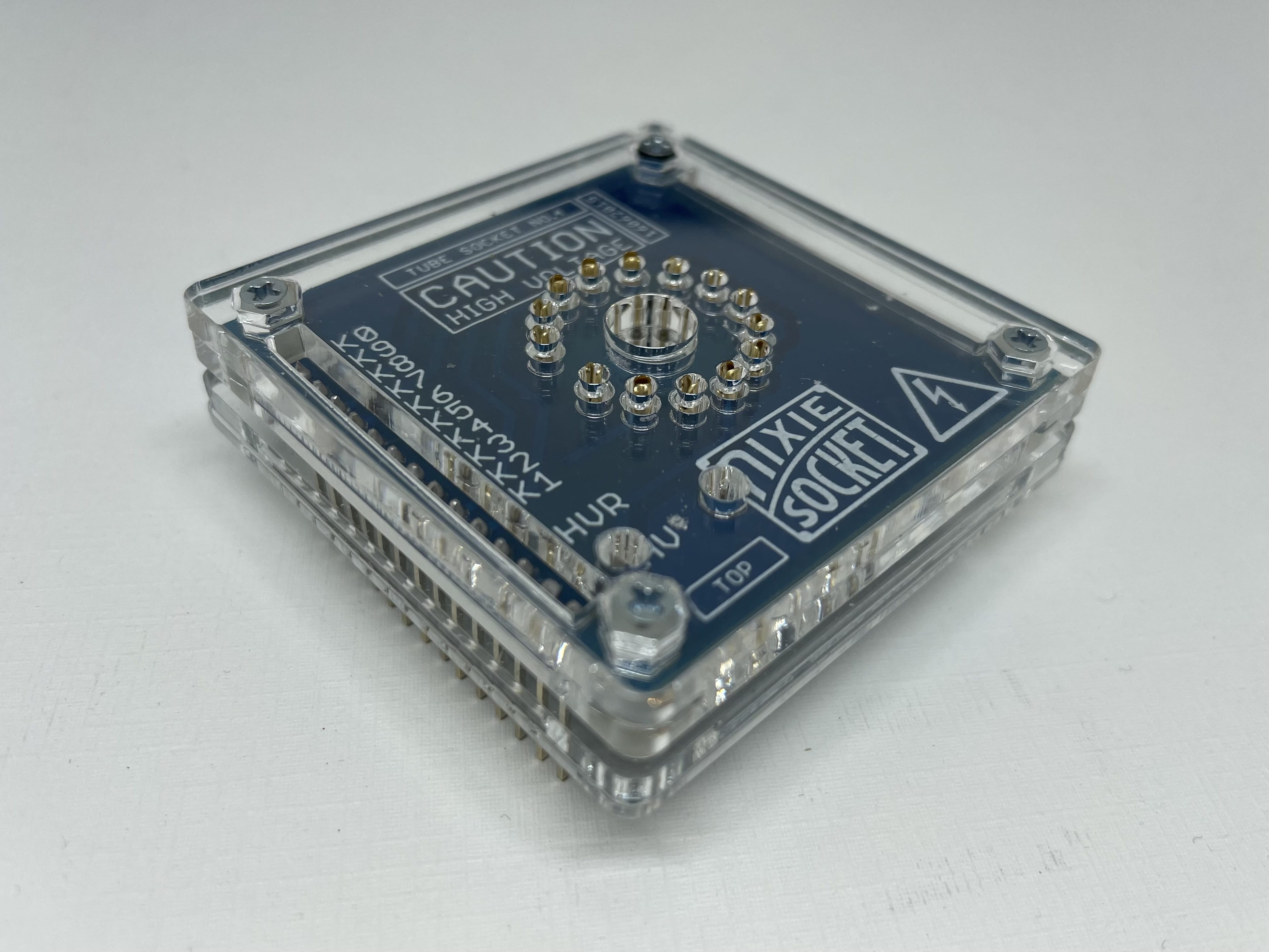
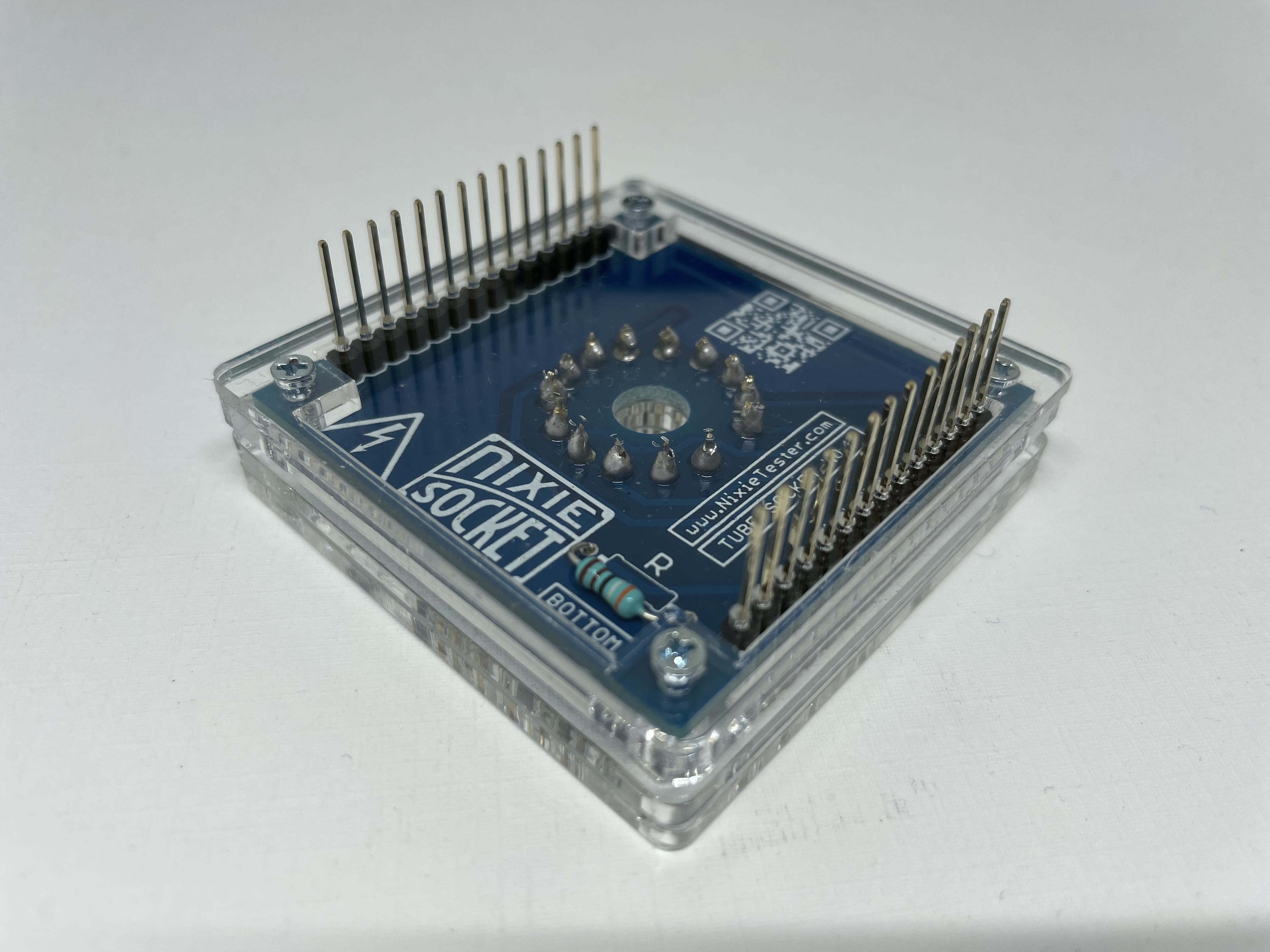
I’ve found that when soldering pin headers, sticking them on a breadboard helps keep them on straight. After I finished assembling it, I had something like this:
Next, I soldered the pin headers on the socket driver board.
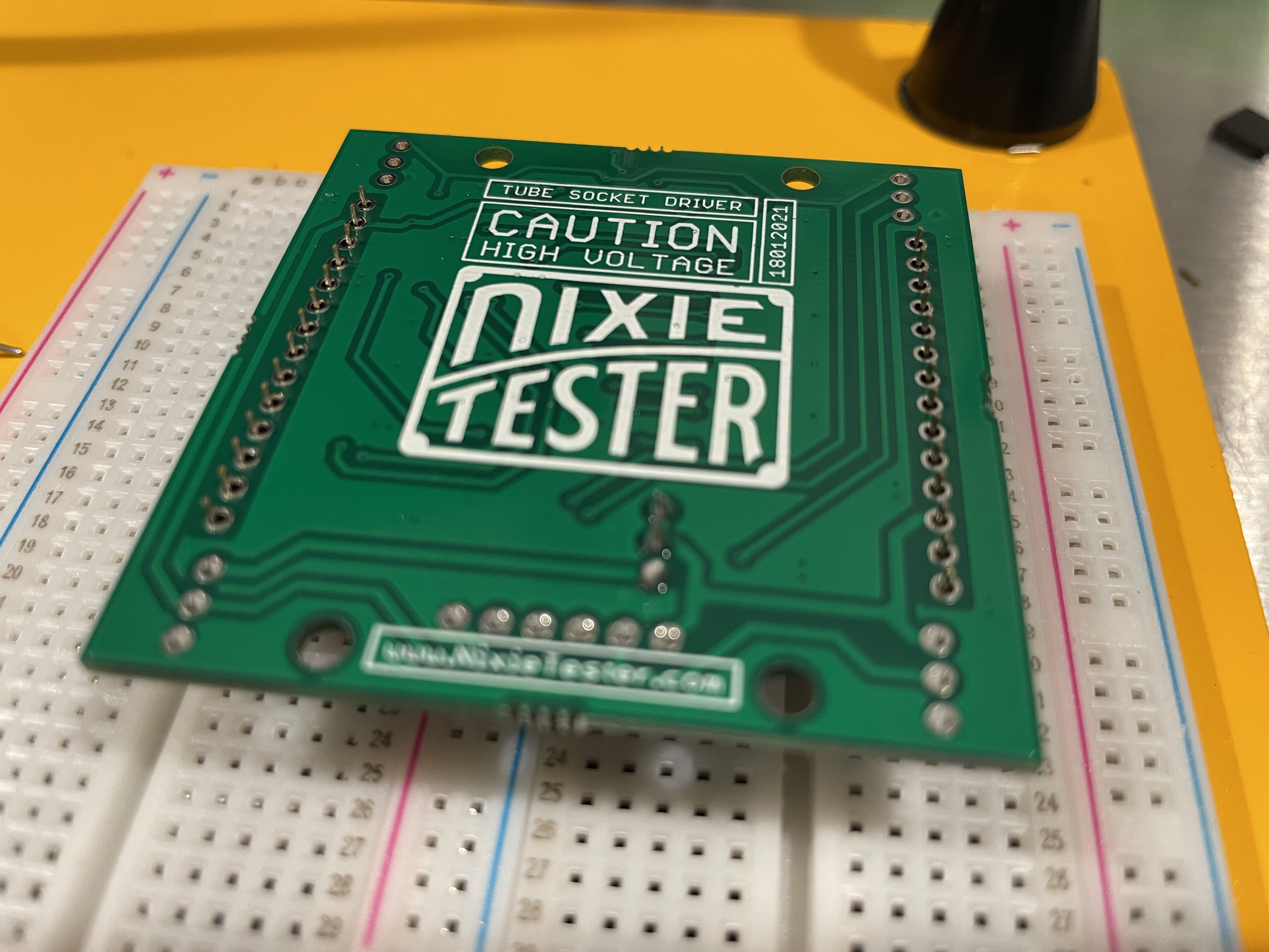
As you can imagine, I was getting pretty tired of soldering by this point. When I was done, my socket driver board looked like this:
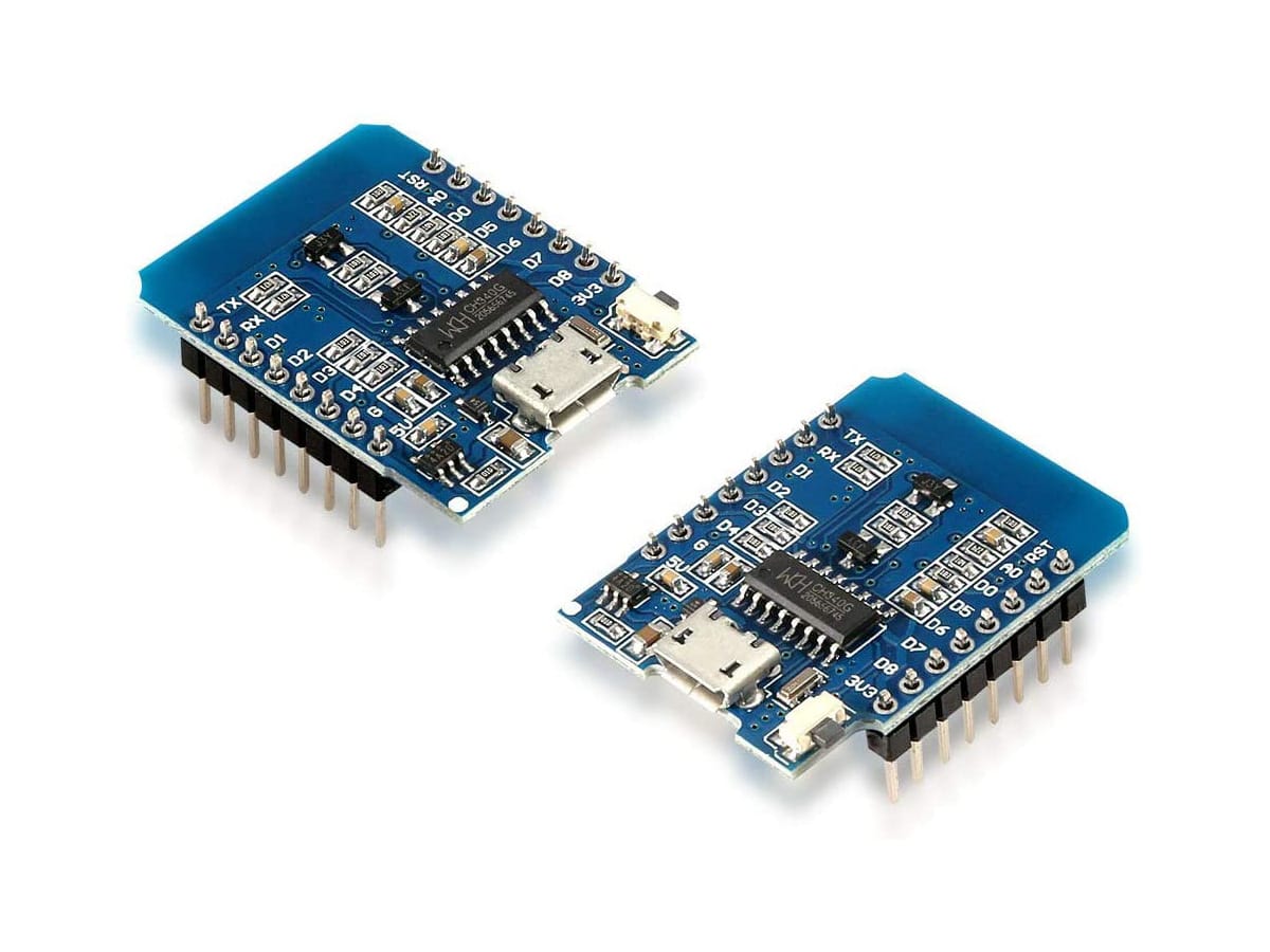
The socket driver comes with example Arduino code for running the board. I took a ESP8266 D1 Mini, soldered the pin headers on, and programmed it with the example code. I set the DIN, CLK, and EN to D2, D3, and D4 respectively.
Let’s take a look at the socket driver board pinout again:
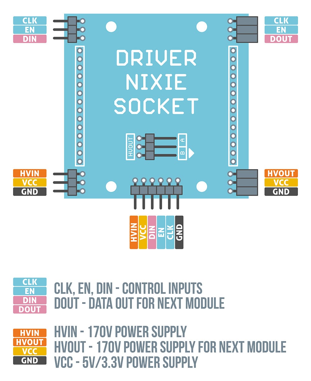
You can connect the inputs on the left side (helpful if you’re running them in serial) or the bottom. I decided to just use the left side.
I connected DIN, EN, and CLK, to D2, D3, and D4 on the D1 mini board. HVIN to HV on the power supply and GND to GND on the power supply. Finally I connected VCC to the 5V on the D1 mini.
| Socket Driver Board Pin | Pin | Board |
|---|---|---|
| DIN | D2 | D1 Mini |
| CLK | D3 | D1 Mini |
| EN | D4 | D1 Mini |
| VCC | 5V | D1 Mini |
| HVIN | HV | Power Supply |
| GND | GND | Power Supply |
It worked! Here’s what it looks like cycling through all the numbers:
Adding an enclosure
I’d been trying to get better at using Fusion 360 for a while but I’ve more or less given up at this point and mostly use OpenSCAD to design now. If you’re struggling with CAD software as well, give it a try, it’s surprisingly intuitive to write code instead of trying to manipulate a model.
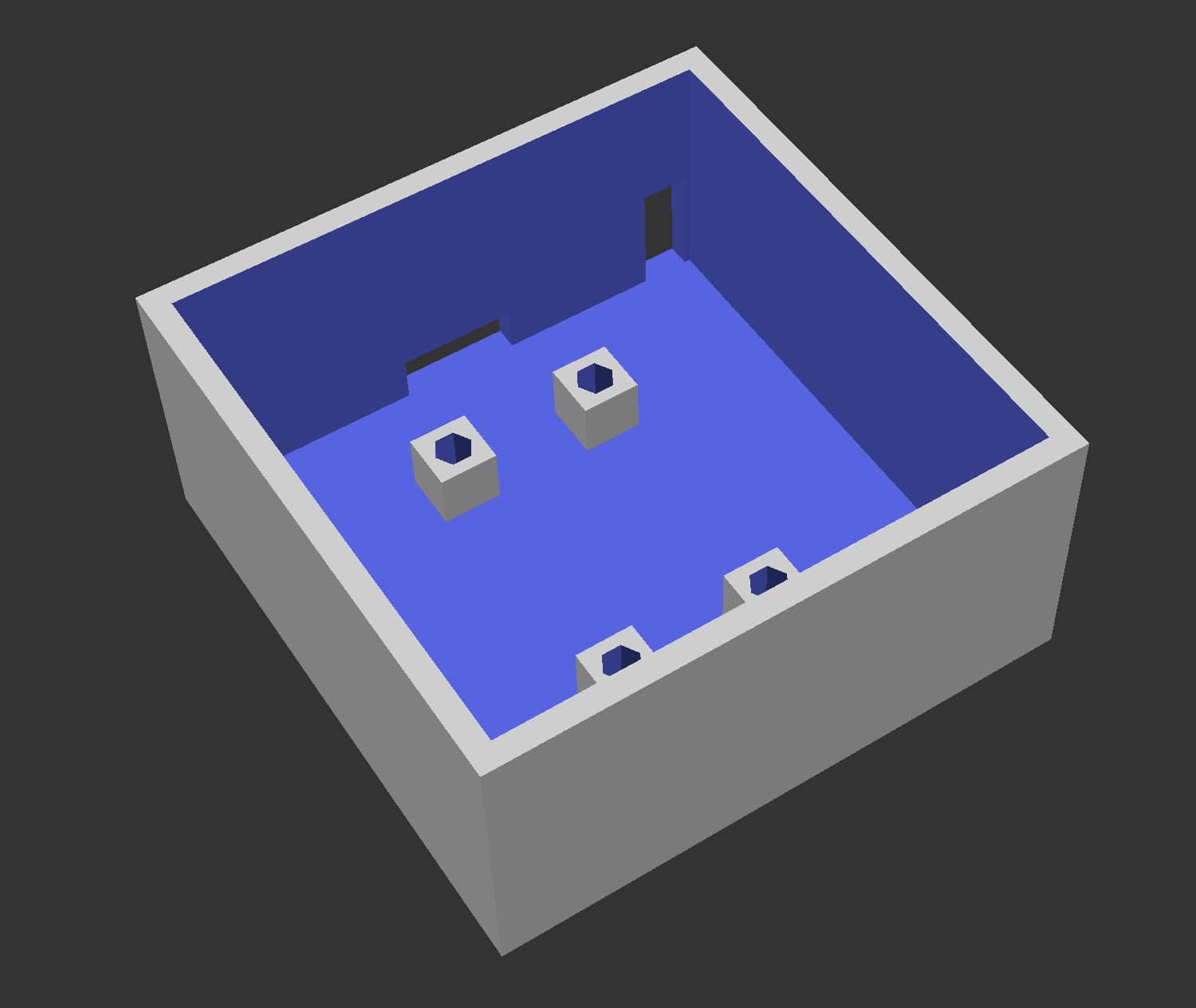
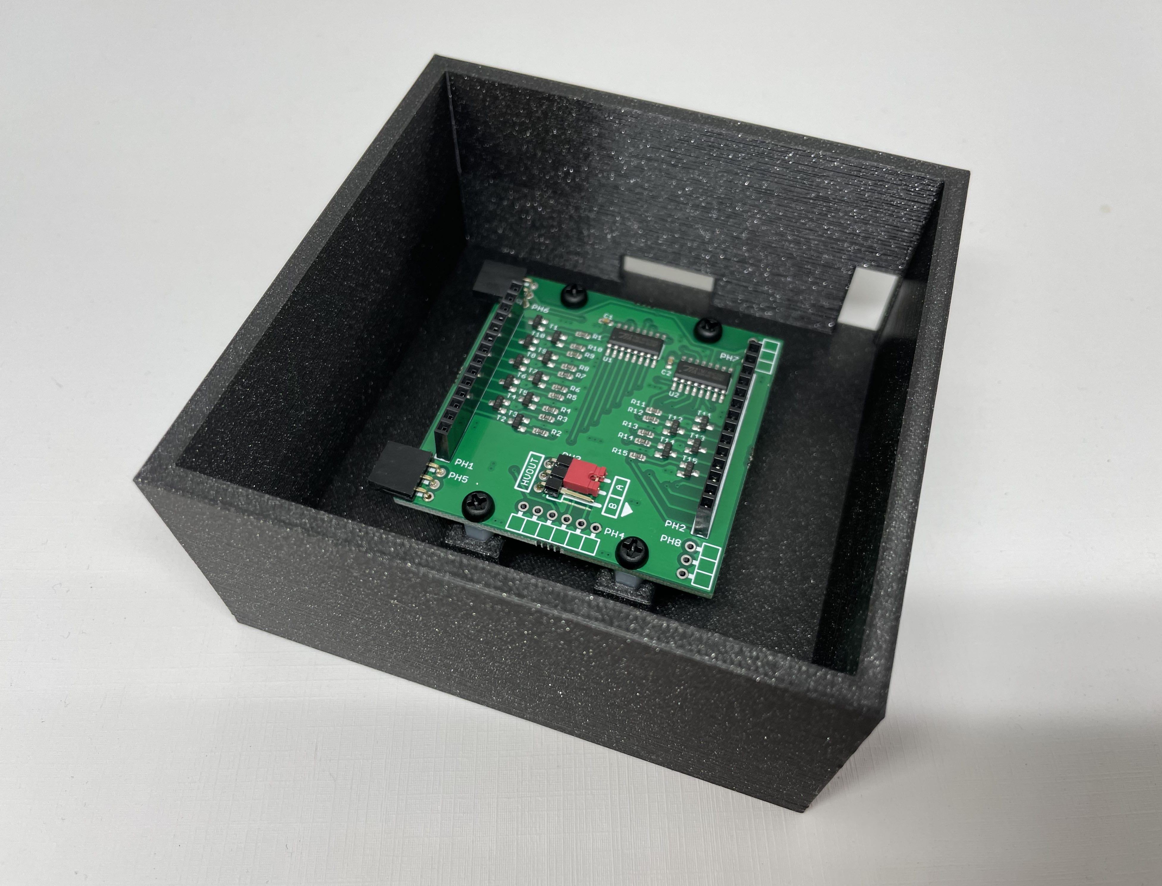
I decided to use the hex standoffs at the bottom of the nixie socket driver board as a way of mounting it onto the enclosure - I made little feet to hold each of them in. Then I cut small holes in the back for both the D1 mini USB input and the cables for the high voltage power.
module stand() {

    difference() {

        difference() {
            cube([100, 100, 48]);
            translate([4, 4, 4])
                cube([92, 92, 48]);
        }

        translate([40, 92, 4])
            cube([20, 20, 8]);

        translate([87, 92, 4])
            cube([8, 20, 20]);

    }

}

module foot() {

    m3nut=6.6;

    difference()
    {
        cube([10, 10, 10]);
        translate([5, 5, 10-8])
            cylinder(d=m3nut, h=8.01, $fn=6);

    }

}


stand();

translate([(100-55)/2 + 9.19, (100-55)/2 - 2.5, 4]) foot();
translate([(100-55)/2 + 26.62 + 9.19, (100-55)/2 - 2.5, 4]) foot();
translate([(100-55)/2 + 9.19, (100-55)/2 + 49.48 - 2.5, 4]) foot();
translate([(100-55)/2 + 26.62 + 9.19, (100-55)/2 + 49.48 - 2.5, 4]) foot();
I printed it with Prusament PLA Prusa Galaxy Black filament, which embeds some glitter in it. After sticking the socket driver board into the enclosure, it looks like this:
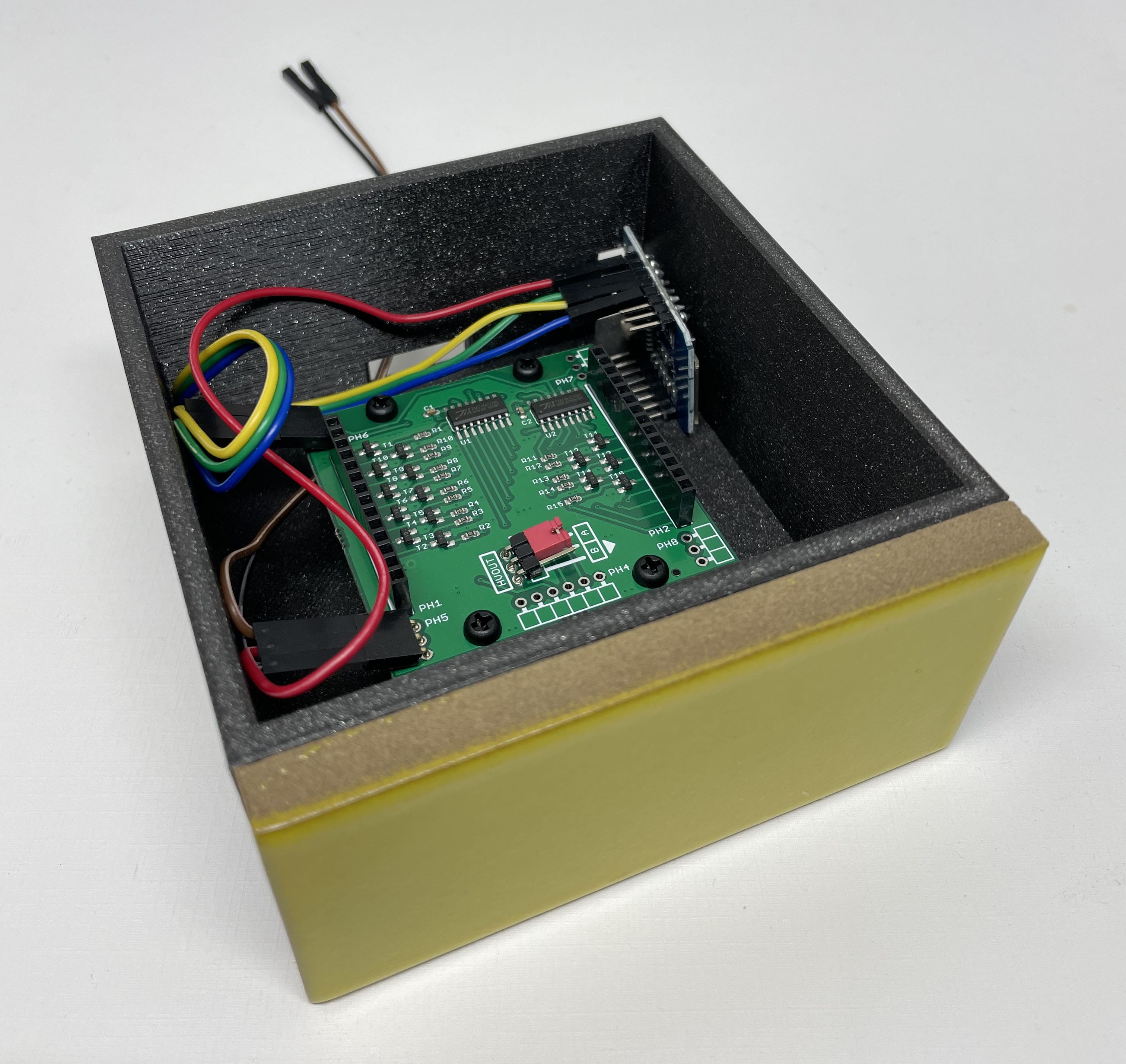
I’d been walking around Heath Ceramics in San Francisco the other day and picked up a few tile samples for $1 each. Pro-tip: If they ask what you’re doing with them, saying something like, “getting some ideas for my kitchen backsplash” will produce less questions than “creating a nixie tube enclosure”.
I stuck one of these tiles to the front with Gorilla Glue, here’s what it looks like with the D1 Mini and power cables installed:
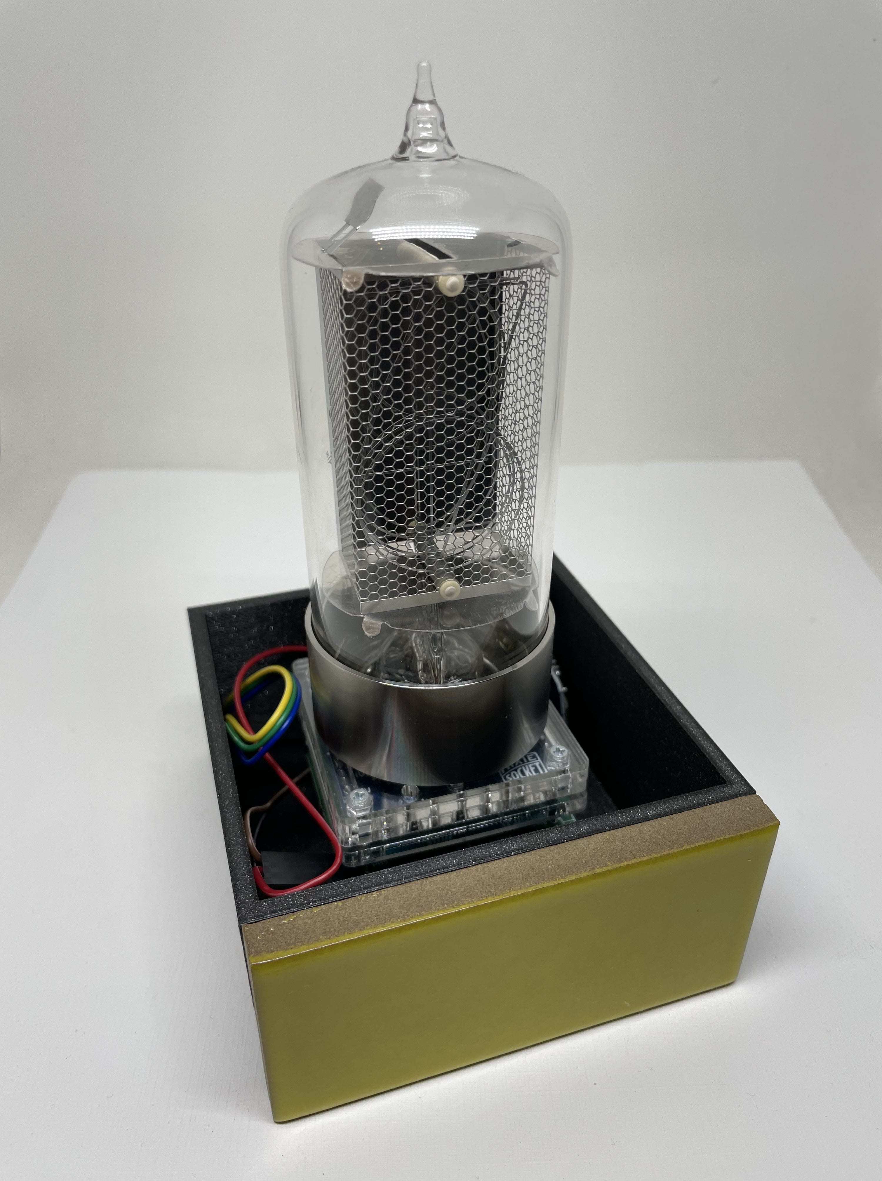
It’s kind of a tight fit in there, I had to bend the 3-pin header connectors on the left upward a bit to actually plug wires into them. Then I put the socket onto the socket driver and the tube onto the socket:
For the cover, I measured the diameter of the tube base and designed this floppy disk looking thing:
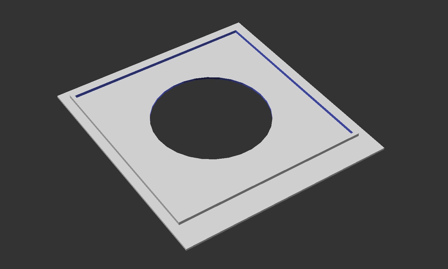
// Cover with the hole cut out for the tube

difference() {
    cube([100, 100, 1], center=true);
    translate([0, 0, -2])
        cylinder(d=54, h=4);
}

// Ridge so that the cover will stay in place

translate([0, 0, 1])
    difference() {
        cube([91.5, 91.5, 2], center=true);
        cube([88, 88, 4], center=true);
    }


// Rectangle in the front for the tile

translate([-50, -50 - 7.55, -0.5])
    cube([100,7.55,1]);
Next I printed it, flipped it over and snapped that into place on top. I didn’t glue it in case I need to perform maintenance:
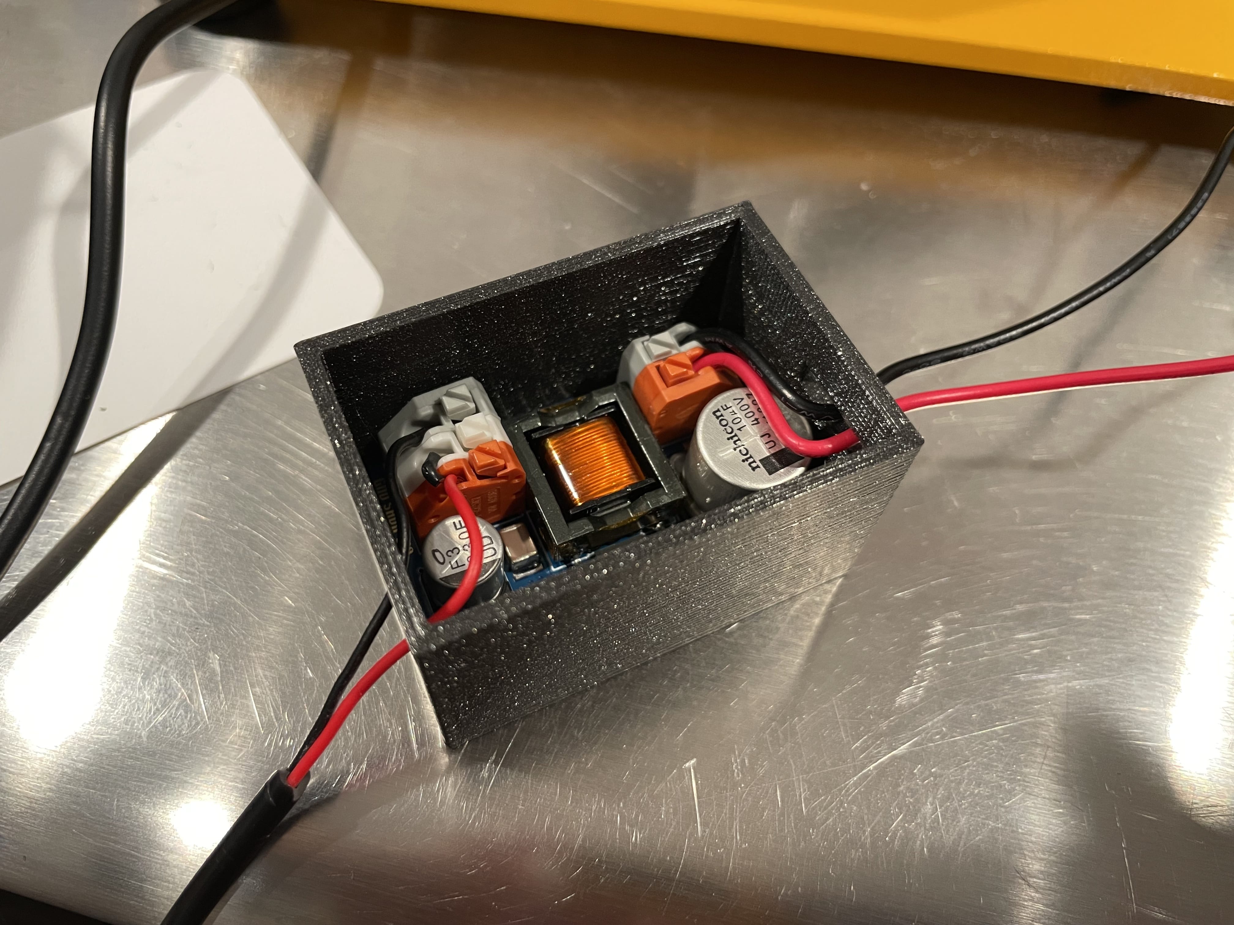
I could have put the power supply into the nixie stand enclosure as well but decided to move it into its own enclosure to save space (perhaps a reason to use the smaller NCH8200HV module instead). I made something similar with cutouts for the input and output wires.
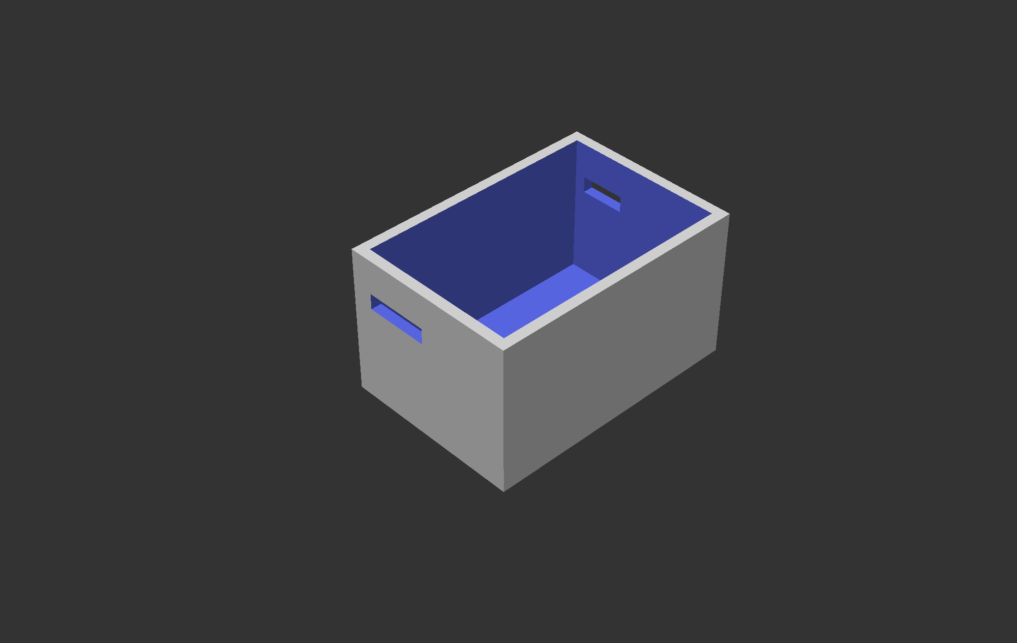
difference() {
    cube([45.5+4,30+4,20+4+4]);
    translate([2, 2, 2]) {
        cube([45.5,30,20+4+4]);
    };
    translate([45.5+2, 21.5+2-2, 16.5+2]) {
        cube([2, 8.5, 3]);
    };
    translate([0, 18, 16.5+2]) {
        cube([2, 12, 3]);
    };
}
It was very difficult to thread the wires through the cutouts, I’d probably make them a bit bigger if I were to do it again.
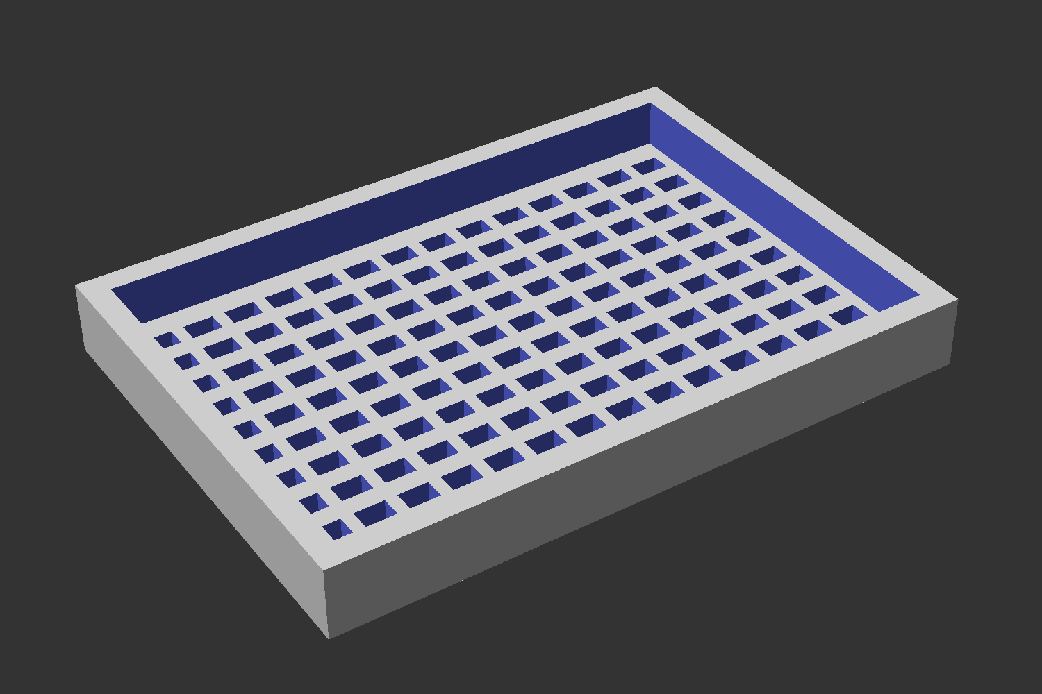
The lid was a little trickier, I wanted to add some holes for heat to dissipate but not big enough to stick my finger in. I’m not sure where I found this fenestration code but it seems to work:
x = 45.5+4;
y = 30+4;
z = 2;

fen_x = 14; // fenestrations on x axis
fen_y = 10; // fenestrations on y axis
fen_size = 5; // size of fenestrations as a % of total axis size

// calculate fenestration size
fen_size_x = fen_size * x / 100;
fen_size_y = fen_size * y / 100;

// calculate space remaining and then divide by number of windows needed + 1 to get the desired size of the struts
strut_x = (x - fen_x * fen_size_x) / (fen_x + 1);
strut_y = (y - fen_y * fen_size_y) / (fen_y + 1);

union() {

    // take away windows from fenestrated surface

    translate([2,2,0]) {
        difference() {
            cube(size=[x, y, z]); // fenestrated surface
            for (i = [0:fen_x - 1]) {
                translate([i * (fen_size_x + strut_x) + strut_x, 0, 0])
                for (i = [0:fen_y - 1]) {
                    translate([0, i * (fen_size_y + strut_y) + strut_x, -1])
                    cube([fen_size_x, fen_size_y, z+2]); // the fenestrations have to start a bit lower and be a bit taller, so that we don't get 0 sized objects
                }
            }
        }
    }

    difference() {
        cube([45.5+4+4,30+4+4,6]);
        translate([2, 2, 0]) {
            cube([45.5+4,30+4,10]);
        };
    }

}
Have you tried turning it on and off again?
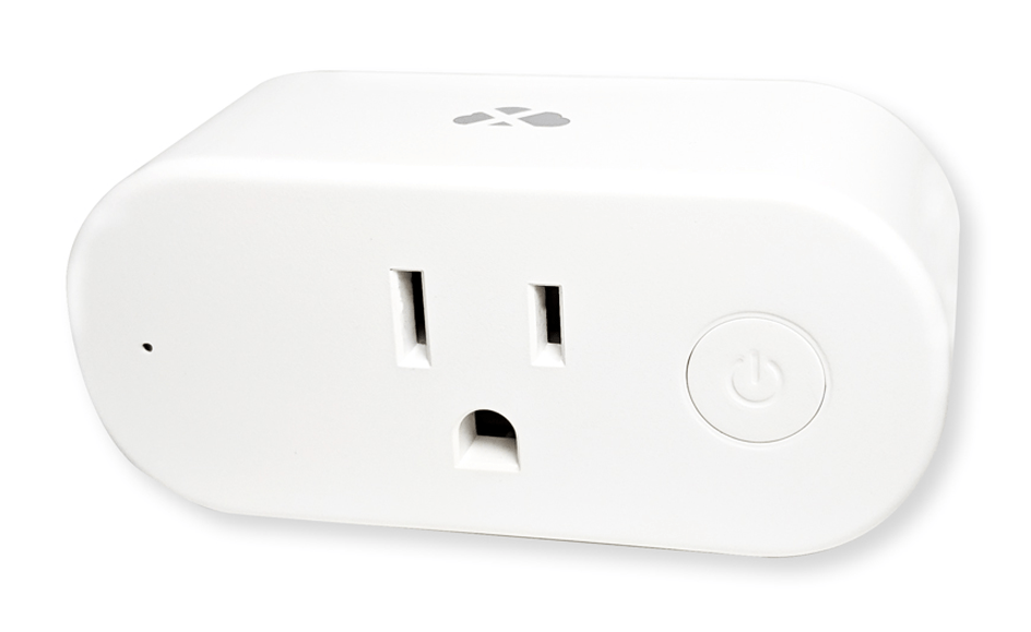
Nixie tubes can last hundreds of thousands of hours but you probably don’t want to just leave them on all the time - you’ll want a way to remotely turn them on and off. For this kind of thing, I’ve been using these smart plugs from Cloudfree (I’m pretty sure Cloudfree is just a guy in college flashing smart plugs between classes): CloudFree Smart Plug 2. They run an open-source firmware called Tasmota which has a little web server that you can access to turn it on and off, but it’s mostly controlled with MQTT, a messaging protocol for IoT devices.
I run Home Assistant on a Raspberry Pi on my network and it can be setup to control these devices. You can also configure schedules so that they turn on and off at certain times.
I found the initial experience of setting up Home Assistant to run a MQTT broker and detect these devices to be pretty confusing, but now that I’ve got it working I’m pretty happy with it.
The steps that I follow to provision new plugs are: plug in the smart plug, connect to the WiFi network (tasmota-xxx), and put in my WiFi credentials. Then I restart it, click Configuration, click Configure MQTT, and change the Host, User, and Password to my MQTT broker. Finally, I go to the console and type SetOption19 1, which enables auto-discovery.
There’s a newer way to integrate Tasmota and Home Assistant with the official Tasmota integration, so maybe it’ll be easier for new users.
After it’s configured as a device in Home Assistant, you can create an access token for Home Assistant by clicking on your profile in the lower left of the web interface, going to the section called Long-Lived Access Tokens, and hitting Create Token.
In Home Assistant, determine the name of your device by clicking on the device and looking for the Entity ID. Mine is switch.nixie_bulb_2.
Now we can toggle the nixie tube on and off by running:
curl -X POST -H "Authorization: Bearer ACCESS_TOKEN" -H "Content-Type: application/json" -d '{"entity_id": "switch.nixie_bulb_2"}' http://homeassistant.local:8123/api/services/switch/toggle
If you want to explicitly turn it on or off instead of toggling, replace toggle with turn_on or turn_off.
Number API
I had programmed the ESP8266 D1 mini to cycle through numbers using the example Arduino code, but once I had verified that it was working, what I really wanted was a way to set the number via an API.
Here’s what I ended up with:
#include <Arduino.h>
#include <ArduinoJson.h>
#include <FS.h>

#include <map>
#include <functional>

#include <UrlTokenBindings.h>
#include <RichHttpServer.h>

using namespace std::placeholders;

#define XQUOTE(x) #x
#define QUOTE(x) XQUOTE(x)

#ifndef WIFI_SSID
#define WIFI_SSID mywifinetwork
#endif

#ifndef WIFI_PASSWORD
#define WIFI_PASSWORD hunter2
#endif

using RichHttpConfig = RichHttp::Generics::Configs::EspressifBuiltin;
using RequestContext = RichHttpConfig::RequestContextType;

SimpleAuthProvider authProvider;
RichHttpServer<RichHttpConfig> server(80, authProvider);

#define DIN_PIN D2 // Nixie socket driver (shift register) serial data input pin
#define CLK_PIN D3 // Nixie socket driver clock input pin
#define EN_PIN D4  // Nixie socket driver enable input pin

// Bit notation of 10-segment tube digits
uint16_t digit_nixie_tube[] = {
    0b0000000000000001, // 0
    0b0000000000000010, // 1
    0b0000000000000100, // 2
    0b0000000000001000, // 3
    0b0000000000010000, // 4
    0b0000000000100000, // 5
    0b0000000001000000, // 6
    0b0000000010000000, // 7
    0b0000000100000000, // 8
    0b0000001000000000  // 9
};

int number = 0;

// Function prototype with optional parameters
void NixieDisplay(int tube1 = 255, int tube2 = 255, int tube3 = 255, int tube4 = 255, int tube5 = 255, int tube6 = 255);

// Function with optional parameters
void NixieDisplay(int tube1, int tube2, int tube3, int tube4, int tube5, int tube6)
{
  StartShiftOutData();
  if (tube6 != 255)
    ShowDigit(tube6); //ShowSymbol(tube6);
  if (tube5 != 255)
    ShowDigit(tube5); //ShowSymbol(tube5);
  if (tube4 != 255)
    ShowDigit(tube4); //ShowSymbol(tube4);
  if (tube3 != 255)
    ShowDigit(tube3); //ShowSymbol(tube3);
  if (tube2 != 255)
    ShowDigit(tube2); //ShowSymbol(tube2);
  if (tube1 != 255)
    ShowDigit(tube1); //ShowSymbol(tube1);
  EndShiftOutData();
}

void ShowDigit(int digit)
{
  ShiftOutData(digit_nixie_tube[digit]);
}

void StartShiftOutData()
{
  // Ground EN pin and hold low for as long as you are transmitting
  digitalWrite(EN_PIN, LOW);
}

void ShiftOutData(uint16_t character)
{
  uint8_t first_half = character >> 8;
  uint8_t second_half = character;
  shiftOut(DIN_PIN, CLK_PIN, MSBFIRST, first_half);
  shiftOut(DIN_PIN, CLK_PIN, MSBFIRST, second_half);
}

void EndShiftOutData()
{
  // Return the latch pin high to signal chip that it
  // no longer needs to listen for information
  digitalWrite(EN_PIN, HIGH);
}

void handleStatus(RequestContext& request) {
  request.response.json["ip_address"] = WiFi.localIP().toString();
  request.response.json["free_heap"] = ESP.getFreeHeap();
  request.response.json["version"] = "builtin";
  request.response.json["number"] = number;
}

void handleSetNumber(RequestContext& request) {
  JsonObject body = request.getJsonBody().as<JsonObject>();

  if (! body["number"].isNull()) {

    if (number != body["number"]) {
      number = body["number"];
      NixieDisplay(number);
    }
    request.response.json["number"] = number;

  } else {
    request.response.setCode(400);
    request.response.json["error"] = "Must contain key `number'";
  }
}

void handlePutNumber(RequestContext &request)
{
  size_t number_to_set = atoi(request.pathVariables.get("number"));
  Serial.println(number_to_set);
  request.response.json["number"] = number;
}

void handleGetNumber(RequestContext& request) {
  request.response.json["number"] = number;
}

void handleStaticResponse(const char* response) {
  server.send(200, "text/plain", response);
}

void setup() {
  Serial.begin(115200);
  Serial.println("Starting up...");

  WiFi.begin(QUOTE(WIFI_SSID), QUOTE(WIFI_PASSWORD));

  authProvider.disableAuthentication();

  server
    .buildHandler("/number")
    .on(HTTP_POST, handleSetNumber)
    .on(HTTP_GET, handleGetNumber);

  server
      .buildHandler("/number/:number")
      .on(HTTP_POST, handlePutNumber);

  server
    .buildHandler("/status")
    .on(HTTP_GET, handleStatus);

  server.clearBuilders();
  server.begin();

  pinMode(DIN_PIN, OUTPUT);
  digitalWrite(DIN_PIN, LOW);

  pinMode(CLK_PIN, OUTPUT);
  digitalWrite(CLK_PIN, LOW);

  pinMode(EN_PIN, OUTPUT);
  digitalWrite(EN_PIN, LOW);

  NixieDisplay(number);

}

void loop() {
  server.handleClient();
}
This uses a library called Rich HTTP Server which lets you build modern REST APIs on ESP8266 devices. It conflicted with some newer ESP8266 libraries, so I had to patch it to get my code to compile correctly.
The code creates a web server with the following API:
- GET /number - Gets the current number being displayed
- POST /number - Sets the current number with the value in the
numberkey in the JSON payload - POST /number/:number - Sets the current number with the value of
numberin the URL path - GET /status - Prints some debug information about the server
Why two ways to set the number? I built the JSON payload one first and then figured I wanted a more lightweight way to call it and ending up leaving both in.
Fidget Device
Now that we have an API for the nixie tube, we can build a simple test case: a fidget device.
I picked up the Stack Overflow The Key macropad when it was released, which probably wasn’t a great purchase, but the build quality was surprisingly good and you can configure it using QMK.

I swapped out the keycaps with some MiTo SA Laser Mitowaves and configured the keys to F13, F14, and F15.
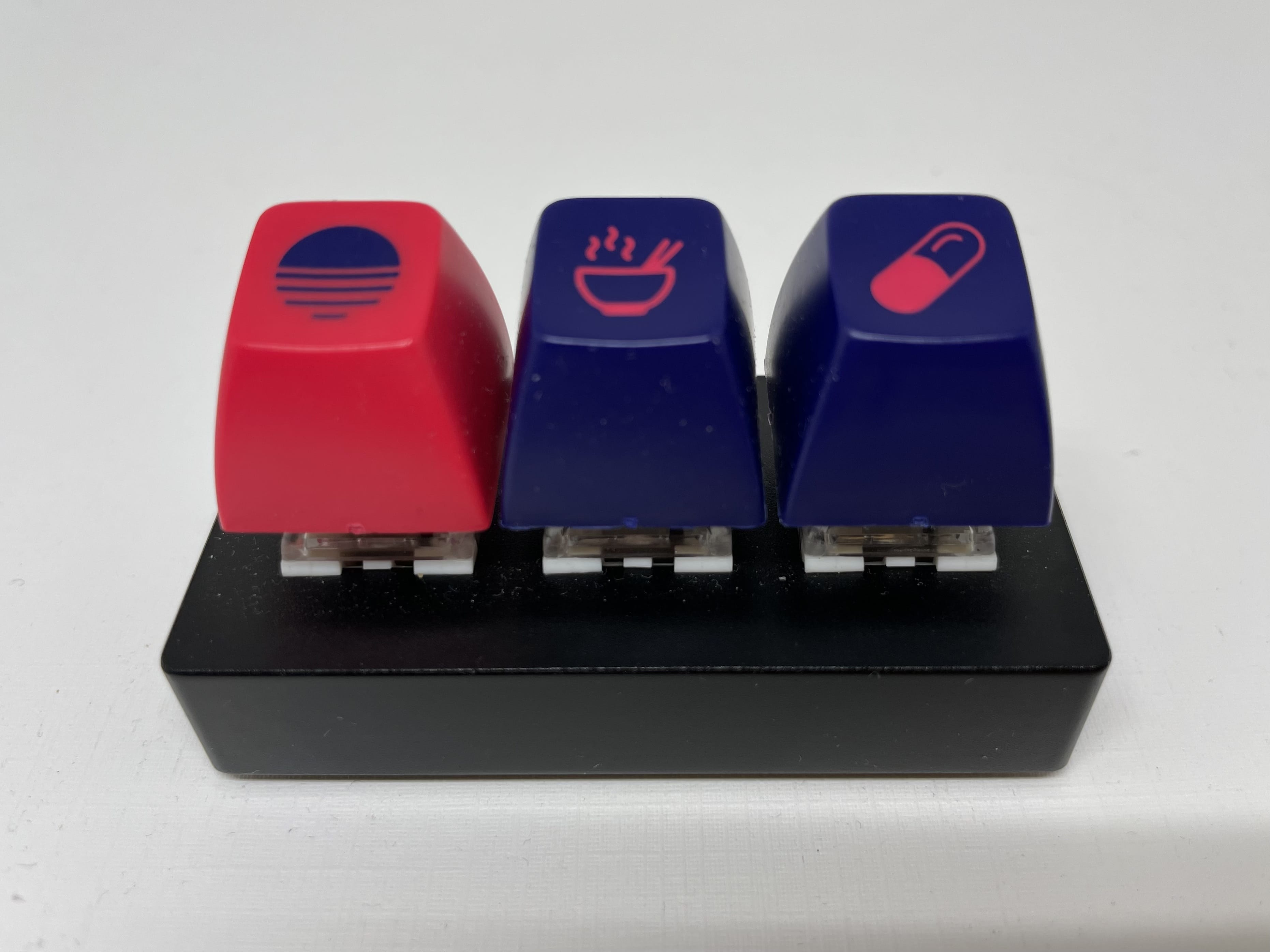
| key | action |
| outrun | toggle the nixie tube on or off |
| ramen | decrement the number |
| pills | increment the number |
Then I configured Karabiner Elements to execute shell scripts when each of them are pressed.
The first script is the same one we saw before, it just toggles the nixie tube on and off:
curl -X POST -H "Authorization: Bearer ACCESS_TOKEN" -H "Content-Type: application/json" -d '{"entity_id": "switch.nixie_bulb_2"}' http://homeassistant.local:8123/api/services/switch/toggle
Since the nixie tube now has an API, we can write a small script called nixie that sets the number by dispatching an HTTP request:
#!/bin/bash
DATA_RAW="'{\"number\": \"$1\"}'"
CURL_CMD="curl --location --request POST 'http://nixie.local/number' --header 'Content-Type: application/json' --data-raw $DATA_RAW --silent > /dev/null"
eval $CURL_CMD
When you type something like nixie 4 and it will set the number 4 on the nixie tube.
Then we can write another script nixie-change that calls the nixie script:
#!/bin/bash
CURRENT=`cat /Users/bert/code/nixie-change/current`
if [[ $1 == 'inc' ]]; then
    ((CURRENT=CURRENT+1))
elif [[ $1 == 'reset' ]]; then
    CURRENT=0
else
    ((CURRENT=CURRENT-1))
fi

if [[ $CURRENT == -1 ]]; then
    CURRENT=9
elif [[ $CURRENT -gt 9 ]]; then
    CURRENT=0
fi

echo $CURRENT > /Users/bert/code/nixie-change/current
/Users/bert/bin/nixie $CURRENT
and set the other two keys to nixie-change dec and nixie-change inc.
It would make a lot of sense to add API methods to increment and decrement the current number, but I was feeling too lazy to actually reprogram the D1 mini, so I just stored the current state locally in the current file.
Here’s what it looks like working together:
Integrating with the TODO list
We could use the fidget device to set the correct number of tasks at the beginning of the day on the nixie tube and manually decrement it each time we completed one, but ideally the nixie tube would just automatically keep in sync with the TODO list.
I currently use Todoist to manage my TODO list. After Wunderlist shut down, I tried a bunch of different apps for my TODO list like Notion, Tot, and Apple Notes, but ultimately found that Todoist met my needs best.
Todoist has a Webhooks API, which allows you to receive an HTTP POST on events that you subscribe to. There are a bunch of different events that you can subscribe to, but I decided to subscribe to these:
| Event Name | Description |
|---|---|
| item:added | An item was added |
| item:updated | An item was updated |
| item:deleted | An item was deleted |
| item:completed | An item was completed |
| item:uncompleted | An item was uncompleted |
In the Todoist Manage App page, it lets you define a Webhook callback URL, but it doesn’t ask you to define a shared secret to help you determine if the request is actually coming from Todoist. So the callback URL itself has to contain a secret. We can generate a new one like this:
cat /dev/urandom |base64|tr -dc 'a-z0-9'|fold -w 32|head -1
Then we’ll stick that at the end of our URL, like this:
https://todoist-webhook-receiver.example.org/process/ddpltohpmme2c7vmr36c6j98fjuevfkz
And write a script to handle this incoming HTTP POST. I wrote this in Deno:
import { Application, Router, Status } from "https://deno.land/x/oak@v9.0.1/mod.ts";
import "https://deno.land/x/dot_env@0.2.0/load.ts";
import ky from "https://cdn.skypack.dev/pin/ky@v0.28.5-EK5VERfsxXvTNWFPnGlK/mode=imports/optimized/ky.js";

const config = JSON.parse(Deno.readTextFileSync('./config/default.json'));

let triggered = false;

const router = new Router();
router
    .post("/process/:secret", async (ctx) => {

        if (!(ctx.params && ctx.params.secret && ctx.params.secret === Deno.env.get("SECRET"))) {
            ctx.response.status = Status.Unauthorized;
            ctx.response.body = 'Unauthorized';
            return;
        }

        const result = ctx.request.body();
        if (result.type === "json") {
            const data = await result.value;

            const validEventNames = new Set(["item:added", "item:updated", "item:completed", "item:uncompleted", "item:deleted"]);

            if (data.event_name &&
                    validEventNames.has(data.event_name) &&
                    data.event_data &&
                    data.event_data.project_id &&
                    data.event_data.project_id == config.project_id) {

                console.log(`Received webhook ${data.event_name} for project_id ${data.event_data.project_id}`);
                triggered = true;

            }

        }

        ctx.response.body = "OK";

    });

const app = new Application();
app.use(router.routes());
app.use(router.allowedMethods());

app.addEventListener("listen", ({ hostname, port, secure }) => {
    console.log(
        `Listening on: ${secure ? "https://" : "http://"}${hostname ??
        "localhost"}:${port}`,
    );
});

const checkAndDispatch = async () => {

    if (triggered) {
        triggered = false;

        const url = `https://api.todoist.com/rest/v1/tasks?project_id=${config.project_id}`;

        try {

            const data = await ky(url, {
                headers: {
                    "Authorization": "Bearer " + Deno.env.get("TODOIST_ACCESS_TOKEN")
                }
            }).json();

            const filteredData = data.filter((task: { section_id: number; }) => (task.section_id == 0));
            const numberOfTasks = filteredData.length;

            console.log(`Number of tasks: ${numberOfTasks}`);

            console.log(`Dispatching to ${config.nixie_relay_url}`);
            await ky(config.nixie_relay_url, {
                method: 'POST',
                json: {
                    number: numberOfTasks,
                }
            });

        } catch (e) {
            console.error('Failed to retrieve tasks', e);
        }

    }
    await setTimeout(checkAndDispatch, 1000);

};

await checkAndDispatch();
await app.listen({ port: config.port });
When the HTTP POST is received, it doesn’t contain the number of tasks in the payload, so we have to make an API call to the Todoist API to get that count. I’ve configured my Todoist project to have a section called “Backlog” that I can move tasks into if I don’t complete them. I don’t want these to count towards the total, so I filter them out.
After it calculates the task count, it dispatches an HTTP request to the nixie tube to update the number. The checkAndDispatch logic is to ensure that if we get a flood of task updates, it still only calculates and dispatches once per second so our API key doesn’t get rate-limited.
Locking it down
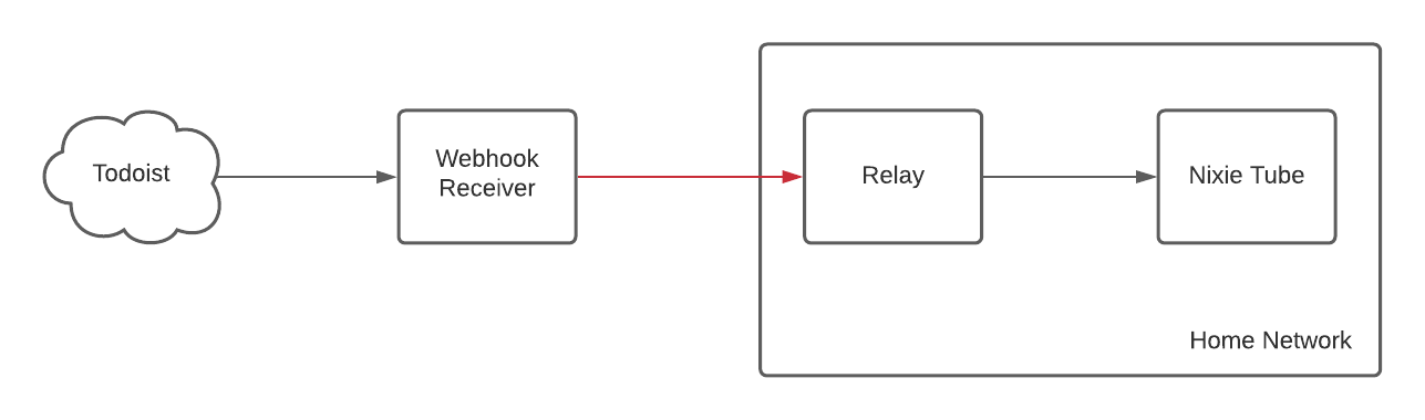
While this setup will work as-is, I don’t like running open web servers on my home Internet connection. If my Internet goes down, the webhook requests would start failing and Todoist might stop sending webhooks to me until I re-enable them. I’ll also have to open a port to the server running this code and something like Shodan will likely pick up the IP and soon I’ll be innudated with requests trying to hack the server.
Ideally I’d like to run this webhook receiver on an external server I control, but it still needs to communicate with the nixie tube to set the number, and I don’t want to open a port to my ESP8266 D1 Mini - that would be even worse.
I’ve been hearing a lot of great things about Tailscale and had been meaning to try it for a while, so I decided to deploy it for this.
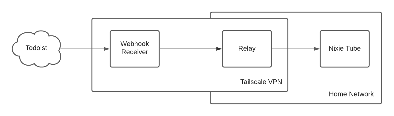
What this does is create a VPN between the external server running the Webhook Receiver and the box in my home network running the relay, which happens to be a Mac Mini. The Mac Mini then exists on two networks, the home network and the VPN. The Tailscale IPs are in the 100.x.y.z range. Setting it up is as simple as downloading Tailscale and running it on both the external server and Mac Mini.
The relay code (also written in Deno), acts as a proxy:
import { Application, Router } from "https://deno.land/x/oak@v9.0.1/mod.ts";
import "https://deno.land/x/dot_env@0.2.0/load.ts";
import ky from "https://cdn.skypack.dev/pin/ky@v0.28.5-EK5VERfsxXvTNWFPnGlK/mode=imports/optimized/ky.js";

const config = JSON.parse(Deno.readTextFileSync('./config/default.json'));

const router = new Router();
router
    .post("/number", async (ctx) => {

        const result = ctx.request.body({ type: "json" });
        const data = await result.value;

        console.log(`Sending ${data.number} to Nixie Tube...`);

        await ky(config.nixie_url, {
            method: 'POST',
            json: {
                number: data.number,
            }
        }).json();

        ctx.response.body = "OK";

    });

const app = new Application();
app.use(router.routes());
app.use(router.allowedMethods());

app.addEventListener("listen", ({ hostname, port, secure }) => {
    console.log(
        `Listening on: ${secure ? "https://" : "http://"}${hostname ??
        "localhost"}:${port}`,
    );
});

await app.listen({ port: config.port });
It just receives the request to set the nixie tube number and replays it to the nixie tube. Note that there is no authentication because this server isn’t exposed to the Internet, it is only accessed via the Tailscale VPN.
The moment you’ve been waiting for
Here you can see me adding a new task to Todoist and the count increasing and then slowly checking off tasks and the count decreasing. There’s a bit of a delay from when you take an action in Todoist to it updating the nixie tube. I ran some tests and the bulk of the latency is actually waiting for the webhook to get sent. The relay over Tailscale and setting the number on the nixie tube is basically instantaneous.
I hope that I never have more than 9 tasks in a day.